

Bare-Metal STM32: Using The I2C Bus In Master-Transceiver Mode
source link: https://hackaday.com/2022/05/11/bare-metal-stm32-using-the-i2c-bus-in-master-transceiver-mode/
Go to the source link to view the article. You can view the picture content, updated content and better typesetting reading experience. If the link is broken, please click the button below to view the snapshot at that time.
Bare-Metal STM32: Using The I2C Bus In Master-Transceiver Mode
As one of the most popular buses today for on- and inter-board communication within systems, there’s a good chance you’ll end up using it with an embedded system. I2C offers a variety of speeds while requiring only two wires (clock and data), which makes it significantly easier to handle than alternatives, such as SPI. Within the STM32 family of MCUs, you will find at least one I2C peripheral on each device.
As a shared, half-duplex medium, I2C uses a rather straightforward call-and-response design, where one device controls the clock, and other devices simply wait and listen until their fixed address is sent on the I2C bus. While configuring an STM32 I2C peripheral entails a few steps, it is quite painless to use afterwards, as we will see in this article.
Basic Steps
Assuming that the receiving devices like sensors are wired up properly with the requisite pull-up resistors in place, next we can begin to configure the MCU’s I2C peripheral. We’ll be using the STM32F042 as the target MCU, but other STM32 families are rather similar from an I2C perspective. We’ll also use CMSIS-style peripheral and register references.
First, we set the GPIO pins we wish to use for the I2C peripheral, enabling the appropriate alternate function (AF) mode. This is documented in the datasheet for the target MCU. For the STM23F042 MCU, the standard SCL (clock) pin is on PA11, with AF 5. SDA (data) is found on PA12, with the same AF. For this we need to set the appropriate bits in the GPIO_AFRH (alternate function register high) register:
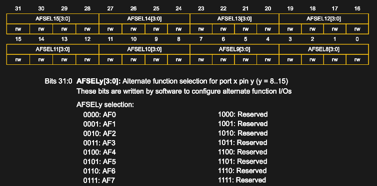
GPIO_AFRH on STM32F042 with AF values.
By selecting AF 5 for pins 11 & 12 (AFSEL11 & AFSEL12), these pins are then connected internally to the first I2C peripheral (I2C1). This is similar to what we did in a previous article on the UART. We also have to enable AF mode for the pin in GPIO_MODER:
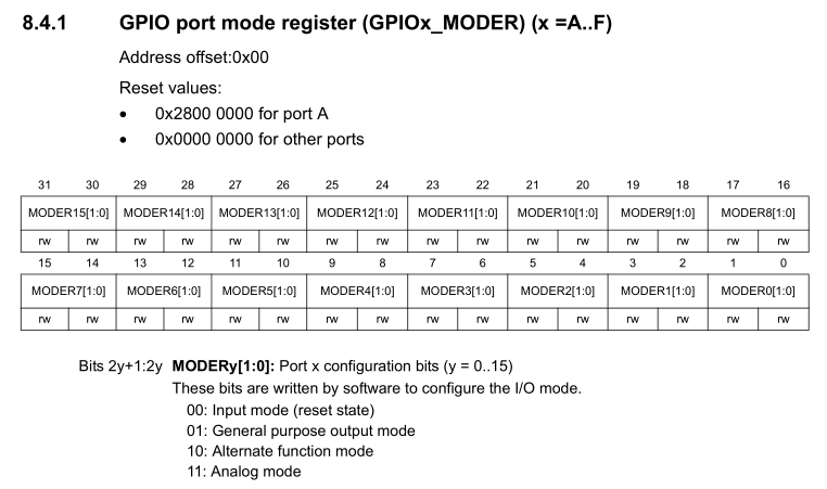
STM32F0x2 GPIO_MODER layout (RM0091, 8.4.4).
All of this is done using the following code:
uint8_t pin = 11; // Repeat for pin 12uint8_t pin2 = pin * 2;GPIOA->MODER &= ~(0x3 << pin2); GPIOA->MODER |= (0x2 << pin2); // Set AF mode.// Set AF mode in appropriate (high/low) register.if (pin < 8) { uint8_t pin4 = pin * 4; GPIOA->AFR[0] &= ~(0xF << pin4); GPIOA->AFR[0] |= (af << pin4); } else { uint8_t pin4 = (pin - 8) * 4; GPIOA->AFR[1] &= ~(0xF << pin4); GPIOA->AFR[1] |= (af << pin4);} |
Note that we want the SCL and SDA pins to be both configured in the GPIO registers to be in a floating state without pullup or pulldown, and in open drain configuration. This matches the properties of the I2C bus, which is designed to be open drain. Effectively this means that the pull-ups on the bus lines keep the signal high, unless pulled down by a master or slave device on the bus.
The clock for the first I2C peripheral is enabled in RCC_APB1ENR (enable register) with:
RCC->APB1ENR |= RCC_APB1ENR_I2C1EN;
Some STM32F0 MCUs have only a single I2C peripheral (STM32F03x and F04x), while the others have two. Regardless, if the I2C peripheral exists, after setting its clock enable bit in this register, we can now move on to configuring the I2C peripheral itself as a master.
Clock Configuration
Before we do anything else with the I2C peripheral, we must make sure that it is in a disabled state:
I2C1->CR1 &= ~I2C_CR1_PE;
The clock settings are set in I2C_ TIMINGR:
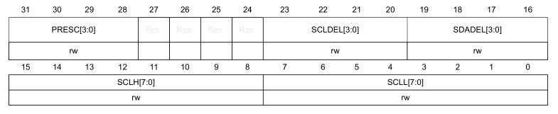
I2C_TIMINGR layout, as per RM0091 (26.7.5)
The reference manual lists a number of tables with timing settings, depending on the I2C clock, e.g. for a 8 MHz I2C clock speed on STM32F0:
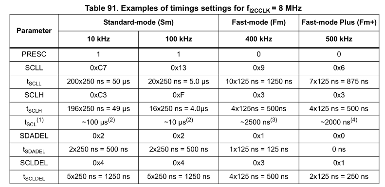
IC2_TIMINGR configuration example table. Source: RM0091, 26.4.10.
This table can be converted into a ready-to-use array of values to configure the I2C peripheral with by putting these values into the right order for insertion into I2C_TIMINGR, e.g. for STM32F0:
uint32_t i2c_timings_4[4];uint32_t i2c_timings_8[4];uint32_t i2c_timings_16[4];uint32_t i2c_timings_48[4];uint32_t i2c_timings_54[4];i2c_timings_4[0] = 0x004091F3;i2c_timings_4[1] = 0x00400D10;i2c_timings_4[2] = 0x00100002;i2c_timings_4[3] = 0x00000001;i2c_timings_8[0] = 0x1042C3C7;i2c_timings_8[1] = 0x10420F13;i2c_timings_8[2] = 0x00310309;i2c_timings_8[3] = 0x00100306;i2c_timings_16[0] = 0x3042C3C7;i2c_timings_16[1] = 0x30420F13;i2c_timings_16[2] = 0x10320309;i2c_timings_16[3] = 0x00200204;i2c_timings_48[0] = 0xB042C3C7;i2c_timings_48[1] = 0xB0420F13;i2c_timings_48[2] = 0x50330309;i2c_timings_48[3] = 0x50100103;i2c_timings_54[0] = 0xD0417BFF;i2c_timings_54[1] = 0x40D32A31;i2c_timings_54[2] = 0x10A60D20;i2c_timings_54[3] = 0x00900916; |
The other options available here are to let the STMicroelectronic-provided tools (e.g. CubeMX) calculate the values for you, or to use the information in the reference manual to calculate it yourself. At this point in time, the Nodate framework I2C implementation for STM32 uses both, with the predefined values as above for STM32F0, and dynamically calculated values for other families.
The advantage of dynamically calculating the timing values is that it doesn’t rely on predefined I2C clock speeds. As a disadvantage there is the additional delay involved in calculating these values, rather than reading them directly out of a table. Whichever approach works best likely depends on the project’s requirements.
With the I2C_TIMINGR register thus configured, we can enable the peripheral:
I2C1->CR1 |= I2C_CR1_PE;
Writing Data
With the I2C peripheral ready and waiting, we can begin to send data. Much like with a USART, this is done by writing into a transmission (TX) register and waiting for the transmission to complete. The steps to following here are covered in the helpful flow diagram provided in the reference manual:
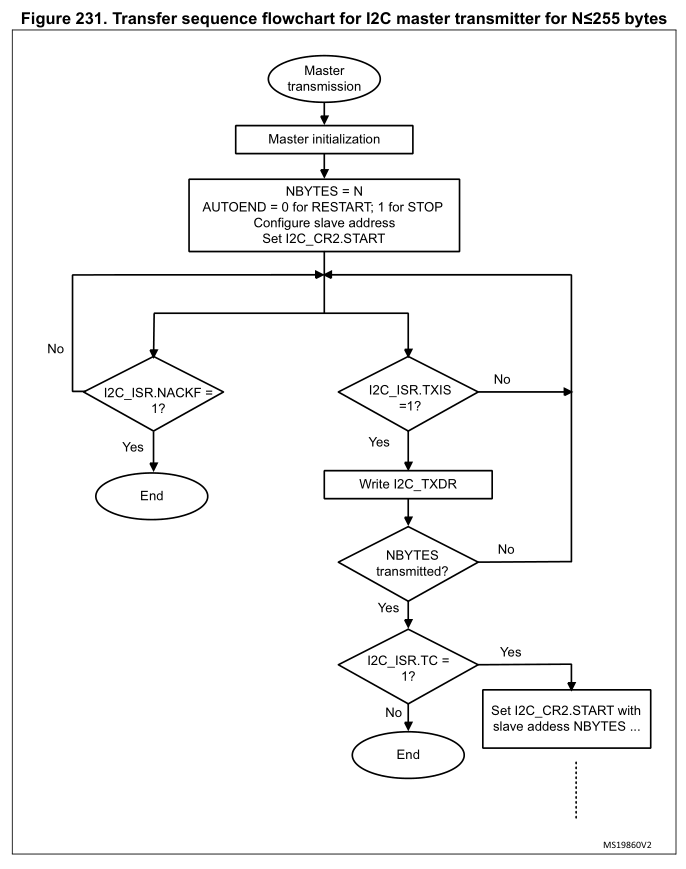
Master transmitter flowchart, reproduced from RM0091.
Worthy of note here is that with some checks, such as for I2C_ISR_TC (transfer complete), the idea is not to check once and be done, but rather to wait with a time-out.
For a simple transfer of 1 byte, we would set I2C_CR2 as such:
I2C1->CR2 |= (slaveID << 1) | I2C_CR2_AUTOEND | (uint32_t) (1 << 16) | I2C_CR2_START; |
This would start the transfer for a total of 1 byte (left-shifted to the NBYTES position in the I2C_CR2 register), targeting the 7-bit slaveID, with the I2C stop condition auto-generated. After the transfer is done (NBYTES transferred), the STOP is generated, which sets a flag in I2C_ISR called STOPF.
When we know we are done with transferring data, we must wait for this flag to be set, followed by clearing the flag in I2C_ICR and clearing the I2C_CR2 register:
instance.regs->ICR |= I2C_ICR_STOPCF;instance.regs->CR2 = 0x0; |
This completes a basic data transfer. For transferring more than a single byte, simply loop the same procedure, writing a single byte into I2C_TXDR each cycle and waiting for I2C_ISR_TXIS to be set (with requisite time-out). To transfer more than 255 bytes, setting I2C_CR2_RELOAD instead of I2C_CR2_AUTOEND in I2C_CR2 will allow for a new batch of 255 bytes or less to be transferred.
Reading Data
When reading data from a device, be sure that interrupts are disabled (using NVIC_DisableIRQ). Generally, a read request is sent to the device by the microcontroller, with the device responding by sending the requested register contents as reply. For example, if a BME280 MEMS sensor is sent 0xd0 as only payload, it will respond by sending back its (fixed) ID as programmed into that register at the factory.
The basic flowchart for receiving from a device looks as follows:
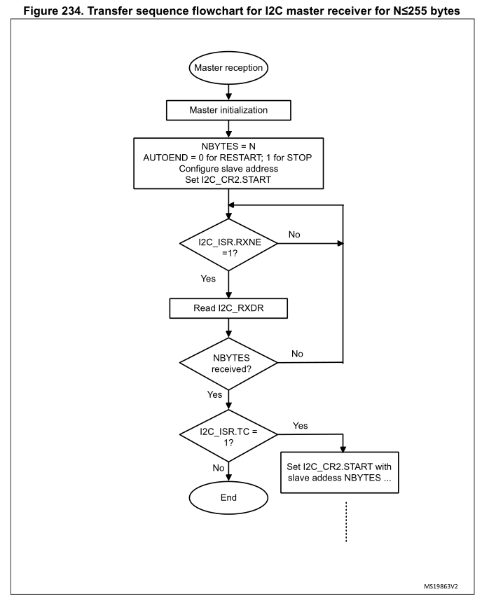
Master receiver flowchart for STM32F0. Source: RM0091.
The basic idea here is the same as with transmitting data. We configure I2C_CR2 in the same manner as before. Main differences here are that we wait for the I2C_ISR_RXNE flag to become unset, after which we can read the single-byte contents of I2C_RXDR into our buffer.
Just like with writing data, after we read NBYTES, we have to wait for the I2C_ISR_STOPF flag to be set, followed by us clearing it via the I2C_ICR register and clearing the I2C_CR2 register.
Interrupt-based Reads
Setting up interrupts with I2C requires us to activate the interrupts for the I2C peripheral in question. This must be done with the peripheral in a disabled state. After this we can enable the interrupt:
NVIC_SetPriority(I2C1_IRQn, 0);NVIC_EnableIRQ(I2C1_IRQn); |
Interrupts are then enabled on the peripheral by setting the configuration bit:
I2C1->CR1 |= I2C_CR1_RXIE; |
Ensure that the appropriately named interrupt handler (ISR) is implemented with the name as specified in the boot-up code:
volatile uint8_t i2c_rxb = 0;void I2C1_IRQHandler(void) {// Verify interrupt status.if ((I2C->ISR & I2C_ISR_RXNE) == I2C_ISR_RXNE) {// Read byte (which clears RXNE flag).i2c_rxb = instance.regs->RXDR;}} |
Don’t forget to add the extern "C" { } block around the handler if using a language other than C to prevent function name mangling.
With this code in place, every time the read buffer receives a byte, the ISR will be called and we can copy it into a buffer, or somewhere else.
Multi-Device Usage
As can be surmised at this point, using multiple devices from a single microcontroller transceiver only requires that the correct device identifier is sent before any payload. This is also where clearing the I2C_CR2 register and correctly setting it the next transmit or receive cycle is essential, to prevent any mix-up in device identifiers.
Depending on the code implementation (e.g. with a multi-threaded RTOS), it’s possible that conflicting reads and writes could take place. It’s essential in this case that I2C writes and reads are coordinated so that no data or commands are lost, or sent to the wrong device.
Wrapping up
Using I2C on STM32 is not very complicated, once one clears the hurdle of setting up the clock configuration. That is a topic which may be worthy of its own article, along with advanced topics pertaining to I2C such as clock stretching and noise filtering. By default the I2C peripheral on STM32 MCUs has a noise filter enabled on its I2C inputs, but these can be further configured as well.
As easy as basic reading and writing is with I2C, there is still a whole rabbit hole to explore, also when it comes to implementing your own I2C device on STM32. Stay tuned for further articles on these topics.
Recommend
About Joyk
Aggregate valuable and interesting links.
Joyk means Joy of geeK