

DIY GSX-R Servo Eliminator
source link: https://forfuncsake.github.io/post/2020/03/diy-gsxr-servo-eliminator/
Go to the source link to view the article. You can view the picture content, updated content and better typesetting reading experience. If the link is broken, please click the button below to view the snapshot at that time.
DIY GSX-R Servo Eliminator
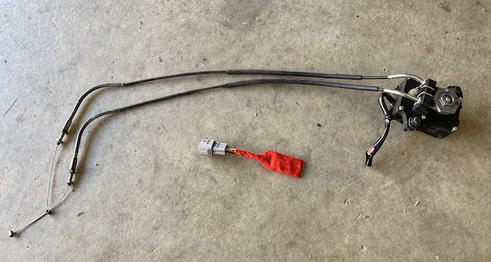
Recently the SET valve servo motor - known in the service manual as the Exhaust control valve actuator (EXCVA) - on my L2 (2012) Suzuki GSX-R750 failed. The initial symptom was a clicking sound during the startup cycle while the ECU tested the valve. The clicking is the result of one of the nylon gears inside the actuator becoming stripped, which essentially means that it’s toast!
There are 3 main options available to deal with this issue:
- Do nothing. Let the valve eventually stop working and ignore the illuminated fault indicator (FI) light.
- Repair/Replace the EXCVA.
- Eliminate the EXCVA with a device that makes the ECU “happy”.
There’s a commercial product known as a Servo Buddy, but they cost more than a few dollars and I’m both cheap and love to have a project to tinker with. I quickly found that that there are already DIY solutions documented, but only for selected makes and models of motorcycle.
GSX-R models up to and including L0 (2010) have a single wire that can be disconnected from the ECU wiring loom to disable both the actuator itself and the startup cycle test, without creating a “fault”. However, servo elimination without buying the likes of a Servo Buddy seemed to be an unsolved problem for the modern GSX-R.
I set about trying to understand how the $9 circuit worked to fool the ECU.. and didn’t get very far. I still have no idea what the purpose of the cap is, but I assume it’s to create a voltage curve over time at the sensor output. Unwilling to blindy feed random voltages into my ECU (and risk letting out the magic smoke) and armed with my toolbox and multi-meter, I got to work on assessing how my bike’s EXCVA actually works.
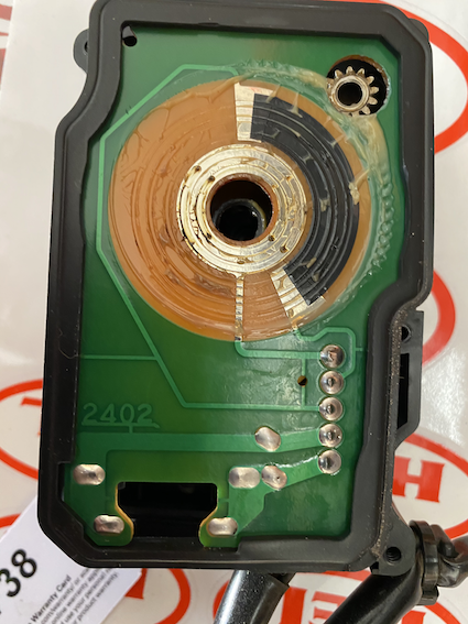
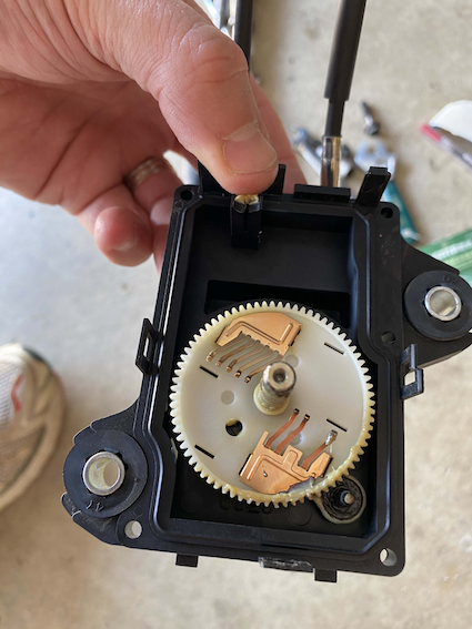
The GSX-R EXCVA is connected to the ECU with 5 wires. Between testing, reading the service manual and opening up the unit itself, I was able to confirm that:
- 2 wires provide +/- 12VDC to drive the DC motor
- 1 wire provides a constant 5VDC
- 1 wire is ground
- 1 wire is input to the ECU sensor pin
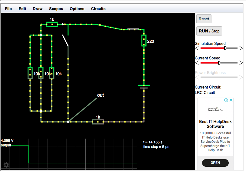
The ECU expects to be able to cycle the valve to fully closed, fully open, about 35% open as part of its startup test. It determines if the test was successful based on the output voltage of the EXCVA, which should be 0.45-1.4V at fully closed and 3.6-4.55V at fully open. Using this awesome circuit simulator, I modeled a voltage dividing circuit with parts I had available at home, then proceeded to build it with a momentary switch (button) to see if a square wave would pass the test.
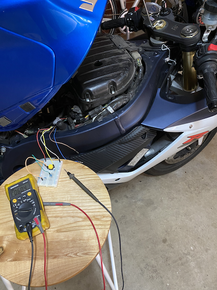
Within a few tries I was able to reproducably start the bike without a fault light by pulling the voltage high (button pressed), dropping to low (button released) approx 400-800ms after turning the key, then returning to high after another 800-1500ms. This confirmed that a square wave was indeed sufficient and that there was likely a high tolerance on the timing.
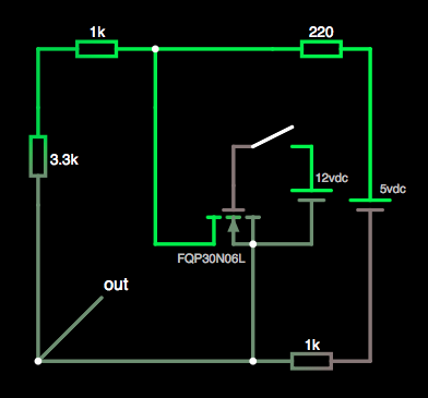
After some distraction reading about 555 timer ICs, then starting to play with the idea of using another NodeMCU ESP8266 board to control the timing, I decided to try and use the 12V line to control the switch (a spare MOSFET I already had) instead of a timer. The experiment was successful, so I got to work on putting it all together.
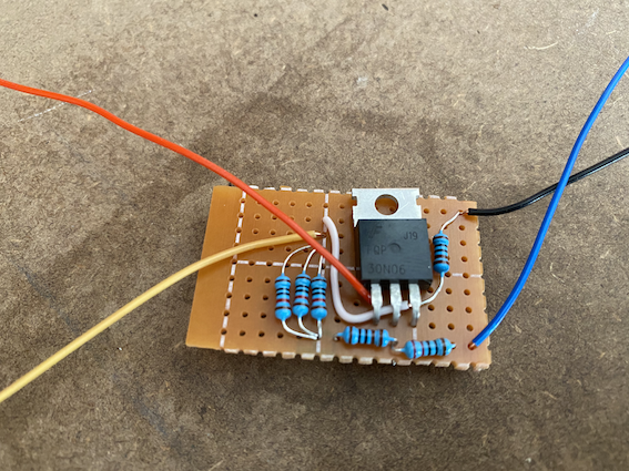
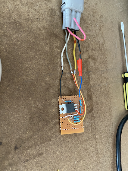
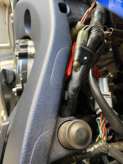
The two following images show how the wires from the board connect up to the plug that was cut from the failed servo motor and the final product installed on the bike, tucked away neatly under the tank. On the plug side: Grey is +12VDC, Black is +5VDC, White is Gnd, Yellow goes to ECU sensor pin.
Note that only one of the 12V wires was needed as we can connect to a common ground, so the output voltage only shifts when the ECU tries to turn the valve in one direction.
The MOSFET specs are significant overkill, but I’m really happy with the result and thrilled to be able to share this solution in the hope that other Gixxer owners will now have another option for removing their servo without a constant FI light, or forking out for a Servo Buddy!
Recommend
About Joyk
Aggregate valuable and interesting links.
Joyk means Joy of geeK