

6502 breadboard computer: part 1
source link: http://www.suppertime.co.uk/blogmywiki/2020/10/6502-breadboard-1/
Go to the source link to view the article. You can view the picture content, updated content and better typesetting reading experience. If the link is broken, please click the button below to view the snapshot at that time.
6502 breadboard computer: part 1
The first computer I ever used, probably in 1977, was my older brother’s KIM-1. This was a bare, single board computer that was really just a development kit for the 6502 microprocessor. It just had 6 numeric LED displays and a hexadecimal calculator-style keypad with some extra buttons for entering, modifying, running and stopping programs running.
You programmed it in machine code – hexadecimal numbers that represented instructions and data. Although time-consuming and difficult, programming the ‘bare metal’ in this way is a great grounding in computer science and coding: it gives you an appreciation of how programs and hardware interact, but more fundamentally, it helps you learn how very much can be achieved with a very limited set of instructions. If you can add, you can subtract, you can multiply and divide, and so on.
The 6502 went on to power the Apple ][, Commodore PET, Commodore 64, Nintendo Entertainment System as well as the Acorn System 1 and the BBC Micro. I soon made the switch from machine code to BASIC, but always hankered after my own KIM-1 or Acorn System 1 - indeed I wish I'd nagged my parents more to but me the latter now, it would have been a pretty good investment. Acorn became ARM, and now almost every human on the planet has one of their microprocessor designs in their pocket. The other thing that stuck with me, coding in BASIC on a PET or ZX Spectrum, was the blinding speed at which machine code routines ran, whether utilities to flip graphics slideshows or entire games.
I previously explored turning a BBC micro:bit into a simple CPU-like machine, but thought for my winter project I'd have a go at building my own breadboard computer, based on the modern version of the 6502, the Western Design Centre W65C02S.
There's quite a vogue for building simple breadboard computers from the ground up, and I can of course recommend Ben Eater's video guides, which I'm using as the basis for my project. I'll be diverging a bit from his path, and I thought it might be worth documenting some of the problems I had along the way. I also highly recommend this single video from Wifi Sheep, who only takes the very first steps but explains everything very well for the non-expert.
Goals
- To learn a bit more about the electronics associated with computer hardware design
- To learn some electronics, full stop
- To re-learn some assembly language for the first time in 40 years
- Maybe eventually to make something with a simple display, keyboard and monitor program that can be programmed like a KIM-1 or Acorn System 1
clock module
Starting with a clock
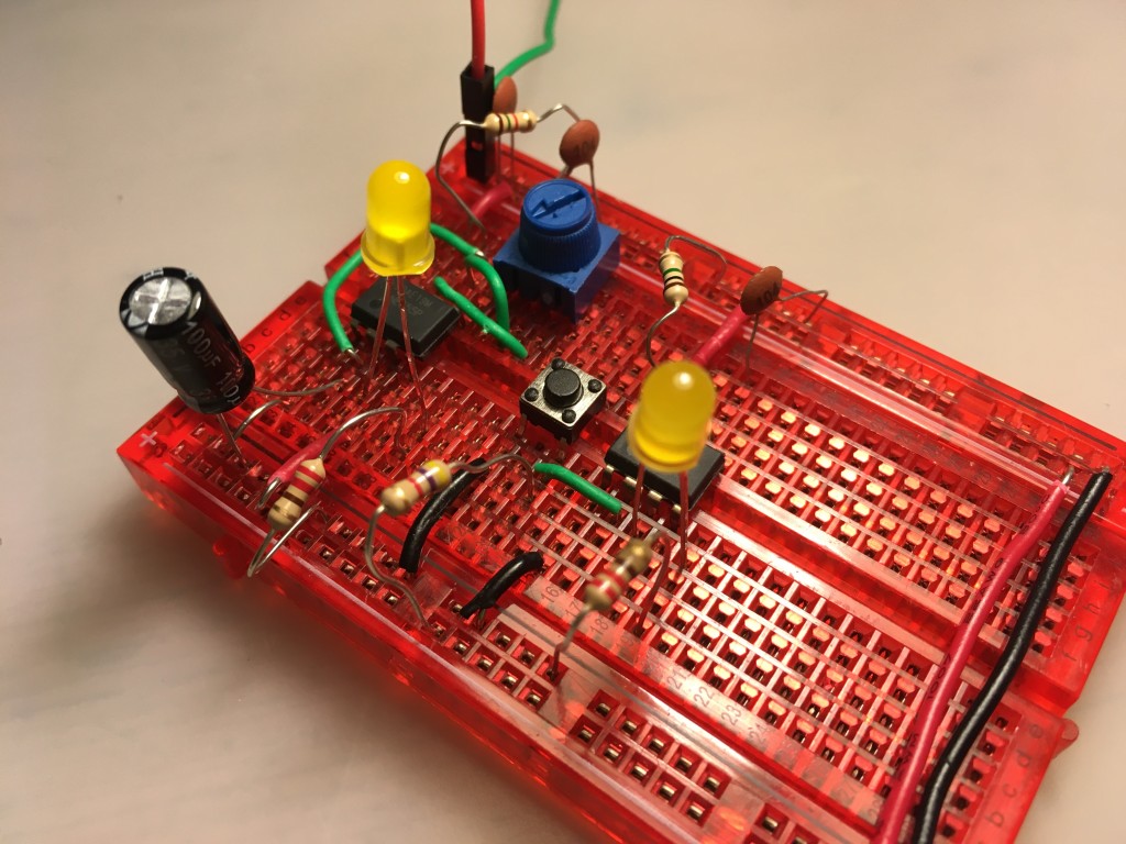
Making a clock seemed like a good place to start. I found Ben Eater’s clock a bit too advanced for my liking, and had originally intended just to have the option either to single-step the processor using a debounced button, or run it at the full 1MHz clock speed using a self-contained crystal oscillator IC.
In the end, I compromised a bit and built a clock using just two 555 timers which I can switch between single-step mode (using the 555 timer for debouncing) and a slow but variable mode which allows you to adjust the clock speed with a variable resistor. It’s basically the first two parts of the Ben Eater clock project, but I didn’t add the extra circuits to combine the logic, and I just added a simple single-pole / dual-throw switch to select which one I want to use. It’s not perfect, but it’s much simpler and more compact that Ben Eater’s, and I still learned a bit about 555 timers, and basic electronics with resistors and capacitors along the way.
Blinking lights!
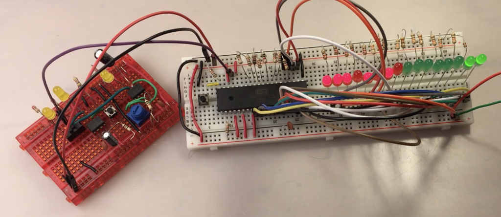
It was now time to bite the bullet and connect up my modern 6502 processor. I ordered most of the bits Ben Eater uses from Mouser Electronics, and some other bits like the wire, LCD display and the EEPROM programmer from various suppliers in China. I guessed a bit, and time will tell whether I actually bought the right chips, I really didn’t have much clue what I was doing!
So, first step was to get some power to the processor, connect some LEDs across the address bus to see if it was alive and if my clock module worked. At first, I couldn’t get anything working at all. It turned out all the anti-static, anti-moisture packaging with its dire warnings had made me over-cautious. I just hadn’t pressed the pins of the CPU chip hard enough into the breadboard and they weren’t making contact.

I connected the pins of the W65C02 CPU like this:

I connected some LEDs across the first few pins of the address bus (pins 9-14), powered both the clock and the CPU breadboard off an old USB lead which I chopped one end off and plugged into an old iPhone charger, and sure enough the LEDs on the address bus blinked madly.
Ordered blinking lights that count
That was quite exciting, but all a bit chaotic and meaningless. Following Ben Eater and Wifi Sheep I then hard-wired a NOP (no operation) instruction to the data bus. This means that the processor has an an instruction to follow, albeit one that does nothing, but it does mean you can see it scanning the address bus in some kind of logical order, and if you single-step the clock you’ll see that each NOP instruction takes two clock cycles to execute. I also added 16 LEDs across the whole address bus so I could see the whole bus being scanned.
You need eight 1k ohm resistors for this. The NOP instruction’s hexadecimal code is EA, which is 11101010 in binary. Starting with pin 26, I connected them like this via 1K resistors
Pin     Connection
26  D7  +5v (1)
27  D6  +5v (1)
28  D5  +5v (1)
29  D4  GND (0)
30  D3  +5v (1)
31  D2  GND (0)
32  D1  +5v (1)
33  D0  GND (0)
Now you can single-step the 6502 through its initialisation sequence, and watch it then settle down to start scanning memory from location EA – and of course, as the single NOP instruction has been hard-wired across its data bus, this is the only instruction it can ever see, so it keeps on counting. It’s quite therapeutic watching the LEDs counting in binary, but next I need to run some real code, which means using some kind of assembler program and programming and adding some memory in the form of an EEPROM… what could possibly go wrong!?
Recommend
About Joyk
Aggregate valuable and interesting links.
Joyk means Joy of geeK