
Even More Bluetooth Smart Bulb Hacking
source link: https://urish.medium.com/even-more-bluetooth-smart-bulb-hacking-fe888a1ab601
Go to the source link to view the article. You can view the picture content, updated content and better typesetting reading experience. If the link is broken, please click the button below to view the snapshot at that time.

Inside the Bulb
First of all, I should say that I found this bulb much easier to take apart compared to the WiFi bulb I worked on previously. By applying just a little force and cutting the red Live power wire from the bulb base, I was able to completely remove the cover and get just the electronics.

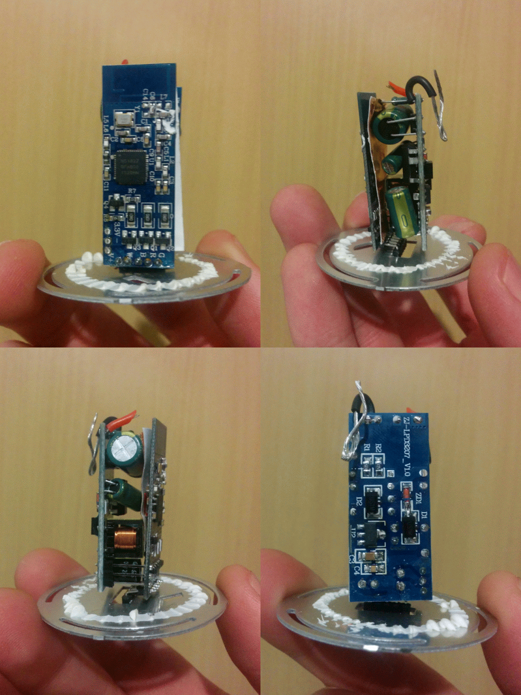
The guts of the bulb consist of 3 parts: the power supply, the logic board and the LED board.

The power supply is connected to the logic board with a 3-pin connector labeled “V+”, “-”, and “3.3V”, which is turn is connected to the LED board by 5 pins labeled “V+”, “W”, “B”, “R”, “G”, which I quickly figured out stand for White, Blue, Red and Green. So far so good.
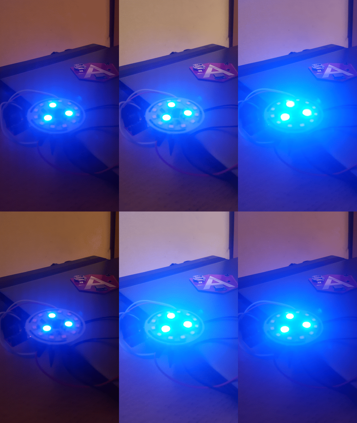
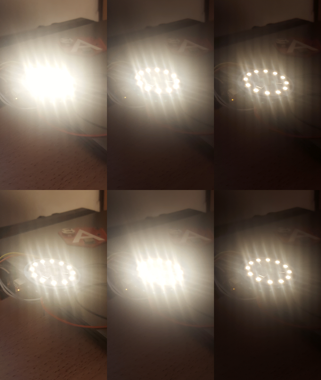
The LED board had 3 RGB LEDs in the center, a ring of 12 warm-white LEDs and some resistors on it.

I decided to cut the pins connecting between the power supply board and the logic board, so I could power it myself and focus on it. I connected a 3.3v power supply to the “3.3V” and “-” pins, ran a quick BLE scan and voila — I could see the bulb.

Not only I could see it, I could even connect to it with both the official app as well as the app I built for the AngularConnect workshop and send some commands.
It seemed like it everything worked, save one thing: there was no light!
Let There Be Light!
I figured out that if I wanted actual light output, I will probably need to supply some power to the “V+” pin, as it is the one that goes to the LED board. I connected that pin to the power supply, and then started from a low voltage, limiting the current to 80mA, and slowly raised the voltage limit. At some point, around 5V, a dim red light started to appear, and as I went up with the voltage knobs, I suddenly got green and then blue. It was working: the bulb circuit was powered. Warm white actually required a little higher voltage; 12V seemed to do the trick.
So, first goal achieved: with a 5V power bank, a 3.3V regulator, and a 12V step-up regulator, I could power the bulb electronics just using battery power.
Now for the fun part!
Getting the Firmware
By looking closely at the logic board, I discovered they used the nRF51822 chip — the same chip I used for the ng-beacon and for the Purple Eye Robot! This is really great for a couple of reasons. First of all, I am already familiar with the chip, and second, it is always fun to see commercial vendors choosing the same products you use in your DIY experiments :-)
Looking closer, I saw that the designers (with whom I’m now thoroughly enthralled) left a small present for me: 3 unsoldered pads that connected directly to the programming interface of the nRF51822 chip!

I quickly soldered a 3-pin header to those pads, connected them to my JLink programmer device, and ran the openocd tool, a free program that allows you to program and debug ARM-based devices:
openocd -f interface/cmsis-dap.cfg -f target/nrf51.cfg -c init;exit
and… it worked! I spotted the following line in the output:
Info : nRF51822-QFAB(build code: C0) 128kB Flash
So it recognized the chip and could communicate with it. Perfect!
Some googling taught me how to dump the firmware from the device:
openocd -f interface/cmsis-dap.cfg -f target/nrf51.cfg -c "init; halt; flash read_bank 0 magicblue.bin 0 131072; exit"
(Note: above is a single line.)
The magic number 131072 is just the size of the flash (128kb in bytes).
The next step was firing up an IDA to look around… But first, I converted the file into the ELF format to make things a little easier (for more info, see my other post):
arm-none-eabi-objcopy -I binary -O elf32-littlearm --binary-architecture arm magicblue.bin magicblue.elf
Playing with the Firmware
Once in the IDA, I switched to Thumb instruction mode (also explained in the WiFi bulb post linked above), and went hunting for strings. There were just a few strings, most of them named the source files of the bulb firmware, but there was one string consisting of the 16 hexadecimal digits: "0123456789ABCDEF":

When you scan for the bulb, you see the name LEDBLE with some hexa-decimal suffix, derived from the Bluetooth address of the bulb (which can confirm against the one we found using the nRF Connect app above). This string looked promising, so I decided to follow the code until I found the function that referenced it. Happily, this quickly turned out to be the code that sets the name of the bulb:

Even if you can’t really read ARM assembly language (not that I am an expert in that) — you can quickly spot how it builds the LEDBLE- suffix for the name of the bulb.
That was a very promising start, and it also confirmed that I was able to extract and load the firmware correctly. Still, I wanted to find the code that handles the actual logic of setting the bulb colors. I could have spent more time wandering through the code, but without almost any strings, it would probably have been a lot of work to figure out the interesting parts, so I decided to use a different strategy — debug the code live on the bulb.
Apparently, the OpenOCD program I used earlier also serves as a GDB Server, meaning you can use the GDB Debugger (as well as other debugger software supporting the GDB protocol) to debug the code as it runs directly on the chip. I downloaded the ARM edition of GDB, ran it and set it up to connect to the chip:
(gdb) target remote localhost:3333
Remote debugging using localhost:3333
0x00000000 in ?? ()
(gdb) monitor reset halt
nrf51.cpu: target state: halted
target halted due to debug-request, current mode: Thread
xPSR: 0xc1000000 pc: 0x000006d0 msp: 0x000007c0
(gdb) continue
Continuing.
The idea was to basically run the bulb code, then randomly stop it and see what code was executing at the time. Repeating this process several times should reveal where the code spends most of the time, which is probably the main loop that controls the device.

I did this, and found two interesting functions at the following memory locations:
00016A6C — This seems to be the main loop of the app, as the apps always stops either inside it, or inside a function that is referenced from it.
00019D82 — The code seems to have a switch table, which means it makes different decision based on some value. Since it seems to spend a lot of time around this function, this might be the code that controls the LEDs and updates them based on the current configuration. Let’s take a closer look:

The code reads some value from the memory address 20002047 (I checked the documentation for the nRF51822 chip, and it says that the RAM is mapped at that address), then loads the value to the register R0, subtracts 0x25 from it and then takes a decision according to that value.
But hold on, 0x25 is the starting index of the bulb lighting mode presets (it goes from 0x25 to 0x38, as we figured out in the previous post). So I thought perhaps this memory address stored the current lighting mode of the bulb.
Luckily, when you debug the live device, it is very easy to check your assumptions. While the bulb ran, I issued the following command in GDB:
set {char}0x20002047=0x28This line is supposed to basically write the value 0x28 to memory address 20002047. It worked! The bulb started fading blue, which corresponds to what it does when it gets the same preset mode number over Bluetooth. Lovely!

I connected to the bulb from the Android app and observed the value of this memory address as I changed the different modes through the app:
print {char}0x20002047As expected, 0x25 to 0x39 corresponded to the fancy preset modes, and 0x4a for the constant color RGB mode, 0x4b to WHITE mode.
Then I made an interesting discovery. By setting the bulb to the warm white mode through the app, then manually changing the value in that memory address to 0x28, I managed to make it fade warm white — a function not supported by the original bulb protocol. Nice!

Trying to write different values to that address while the bulb is in Warm White mode revealed something interesting: it seems like the warm white kicks-in in place of the blue color. So if I write the value 0x2e, which corresponds to cross-fading between Red and Blue function, it will actually fade between Red and White.
Concluding Thoughts
Overall, the live-debugging method proved itself as a very efficient reverse-engineering technique: it took me just a little more than one hour from the moment I connected the debug interface until I could do the things mentioned above. It kept me focused on the more interesting parts, and I had to read almost no unrelated code.
So checking in with my second goal, I almost managed to mix Warm White with RGB, just without the Blue :) Good enough for now!
As you might have gathered from my last post, I’m going to focus more on the ng-beacon project, so I won’t be coming back to this project any time soon. That said, I think the next steps for this project would be to try and figure out a way to enable RGB+W by uploading a patched firmware, or to create new firmware from scratch and upload it to the device to enable the RGB+W “mode.”
Maybe someday, if Bluetooth SIG ever releases a standard to control smart bulbs, we will even be able to align the bulb with that standard. Until then, we’ll keep smart bulb hacking simmering on the back burner…
Recommend
About Joyk
Aggregate valuable and interesting links.
Joyk means Joy of geeK