

Network Analysis in Electric Circuits
source link: https://www.geeksforgeeks.org/network-analysis-in-electric-circuits/
Go to the source link to view the article. You can view the picture content, updated content and better typesetting reading experience. If the link is broken, please click the button below to view the snapshot at that time.
Network Analysis in Electric Circuits
In this Article We will be going through what is Network Analysis, we will look at its components,then we will go through Electrical Elements, In this we will Know what is active and passive elements and the Different types of connections in electrical circuits, Next we will go through Different types of laws and Solved Examples on it, Similarly we will go through different theorems and at last we will conclude this article with Advantages, Disadvantages, Applications, and FAQs.
What is Network Analysis?
In electrical engineering, a network is defined as a collection of electrical components (like resistors, capacitors, etc.) inter-connected to form an electric circuit. The process by which we analyze or calculate different electrical parameters of the circuit like voltage, current, and power is called network analysis. There are various methods and techniques through which we can determine the electrical parameters. These methods include Ohm’s Law, Kirchhoff’s Law, Nodal Analysis, Mesh Analysis, and so on.
Let’s look at some of the important terms that we use in network analysis
• Node: It is a point at which the terminals of more than two components are connected.
• Branch: It is a connection between two nodes.
• Mesh: It is a group of branches joined to form a complete loop in a network such that there is no loop inside it.
• Component: It is a device that has two or more terminals into which the current may or may not flow.
• Port: Two terminals where the incoming current is equal to the outgoing current in the other.
• Circuit: A circuit is defined as a closed loop through which an electric current can flow.
Electrical Elements
Electric circuits consist of two types of elements – Active elements and Passive elements.
Active element: The elements that are capable of generating or supplying electrical energy.
Ex: voltage source and current source, oscillators, etc.
Passive element – The elements which do not generate electricity but either consume it or store it.
Ex. -Resistors, Inductors, Capacitors, etc.
Let’s look at some of these elements
• Resistor : It is a device that limits, regulates or reduces the flow of electric current.
• Inductor : It is a device that stores energy in magnetic field when current flows through it.
• Capacitor: It stores energy in the form of charge in an electric circuit.
• Current source : It is a source that is independent of the voltage across it and provides current that remains constant.
• Voltage source : It is a source which is independent of current drawn and the voltage across it is always constant.
Series and Parallel Connection
- Series connection – If the current flowing in a circuit is same through all the components, then the circuit is said to connected in series connection. As the name suggests the components in a series circuit is connected in a line
- Parallel connection – If the current has different paths to flow through then the circuit is said to be connected in parallel connection. As the name suggests the components in parallel circuit are connected parallel to each other.
Different Laws in Network Analysis
Different Types of the Laws in Network Analysis are:
- Ohm’s Law
- Kirchhoff’s Laws
Ohm’s Law
It states that if all physical conditions and temperatures remain constant then the voltage across a conductor is directly proportional to the current flowing through it.
Mathematically , V=IR
Where,
V=Voltage,
I=Current,
R=Resistance
Solved Example
Q .What is the current flowing through a circuit having 500 ohms resistor and 10 volts voltage source
According to Ohm’s Law – V=IR and I=V/R
I=10/500=0.02A
Hence current is 0.02A
Kirchhoff’s Laws
Kirchhoff’s laws are referred to as the two fundamental principles in electrical circuit theory. There are two laws of Kirchhoff – Kirchhoff’s Current Law (KCL) and Kirchhoff’s Voltage Law (KVL). Let’s take a look at these in detail.
Kirchhoff’s Current Law
Kirchhoff’s Current Law states that the total current entering a junction or a node is equal to the total current leaving that junction or node. It principally states that the algebraic sum of current entering and leaving any junction is always zero. This law is based on conservation of charge.
Mathematically, Σ i = 0 (incoming current = outgoing current)
Kirchhoff’s Voltage Law
Kirchhoff’s Voltage Law states that the algebraic sum of voltage around a loop or a closed path equals to zero. It principally, states that total energy supplied by the voltage sources in a closed loop is equal to the total energy consumed by the circuit elements in that loop. This law is based on conservation of energy.
Mathematically, Σ v = 0 (voltage across a loop = zero)
Solved Example
Q. What is the voltage VS across the open switch in the circuit shown in fig given below

Kirchhoff’s Law
We will apply KVL to find VS. First, we will start from point A and then move in the clockwise
direction to calculate the total voltage.
Vs + 10 – 20 – 50 + 30 = 0 . Therefore, Vs = 30V .
Theorems Used for Electrical Circuit Network Analysis
Different Types of Theorems in Electrical Network Analysis are
- Superposition Theorem
- Thevenin’s Theorem
- Norton’s Theorem
Superposition Theorem
Superposition Theorem states that if a linear network contains multiple (two or more) independent sources, the resultant current/voltage in any branch will be equal to the algebraic sum of the currents/voltages due to independent sources acting alone. The rest of the independent sources being replaced by their respective internal resistances.
Procedure for using the Superposition Theorem
In order to find the contribution of voltage or current source, the other independent sources needs to be deactivated. In case of voltage source it is replaced by short circuits, whereas the current sources are replaced by open circuits. This process has to be repeated for each source and the response needs to be calculated. Once all the responses are calculated the total response can be calculated by taking the algebraic sum of each of the individual responses.
Solved example
Q. Use the superposition theorem to find v in the circuit shown
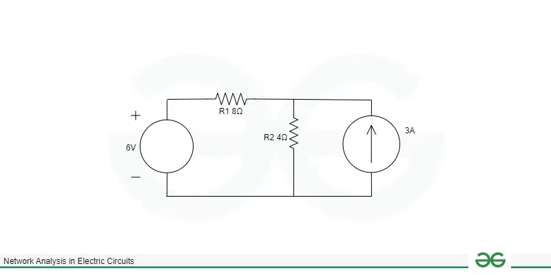
Superposition Theorem
V1 = 4i1 = 4 X (6/12) = 2V
Consider current source only (voltage source 6V is discarded by short circuit)
V2= 4i3 =4 x (3 x 8/12) = 8V
Total voltage V=V1+V2 = 10V
Thevenin’s Theorem
Thevenin’s Theorem states that any linear two–terminal circuit consisting of several voltages and resistances can be replaced by a single voltage (Vt) in series with a resistance connected across the load (Thevenin Resistance).
Here Vt is open – circuit voltage at the terminals.
Steps for using Thevenin’s Theorem
Step 1: First, we will remove the Load Resistor from the circuit.
Step 2: Then we will Calculate the Thevenin Voltage.
Step 3: Replace the power sources with short circuit wires.
Step 4: Calculate the Thevenin Resistance.
Step 5: Draw the Thevenin Equivalent Circuit.
Solved Example
Q. Find the Current I Through R=2Ω for The Circuit given below using Thevenin’s Theorem
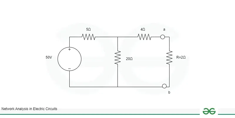
Thevenin’s Theorem
After Removing R=2Ω Circuit will be

Circuit
-50+25I=0
Hence,VabV_{ab}
Vab=20xI=40V
To find RthR_{th}
Rth we deactivate Voltage Source
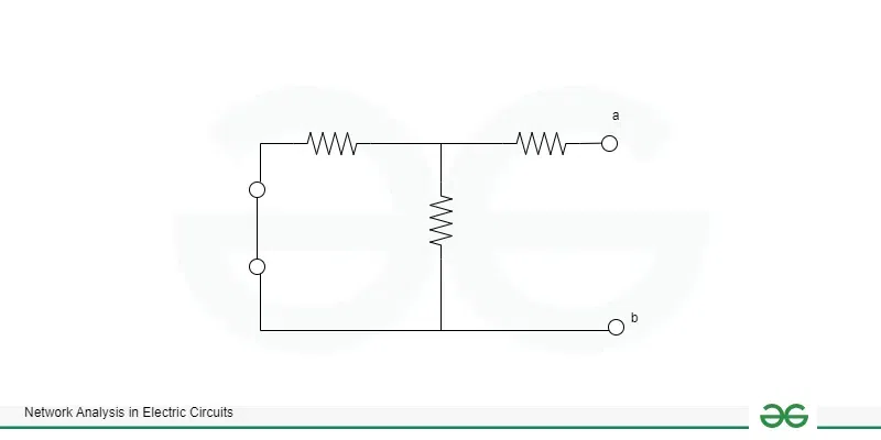
Circuit
RthR_{th}
Rth=(5Ω||20Ω)+4Ω
RthR_{th}
Rth=8Ω
So the Thevenin’s Circuit will be

Circuit
I=4010=4VI=\frac{40}{10}=4V
I=1040=4V
Norton’s Theorem
Just like Thevenin theorem, Norton’s Theorem helps in simplifying a complex electrical circuit. Norton’s Theorem states that any linear two-terminal electric network which contains several sources, can be replaced by an equivalent circuit consisting of a single current source in parallel with a resistor. The resistance will be equal to the resistance at the terminals when the independent sources are turned off and the current will be equal to the short-circuit current through the terminals. Norton’s Theorem is also referred to as “dual of Thevenin’s Theorem”.
Procedure for using Norton’s Theorem
The first thing that needs to be done is identifying the circuit and removing the part where the Norton equivalent has to be calculated (load resistor). Instead of the load resistor, that part will be replaced by a short circuit. After this step, current flowing through the short circuited part needs to be calculated. The calculated current is called Norton current. Once the current is calculated, all the sources have to be replaced. The voltage sources will be replaced by short circuits and all current sources will be replaced by open circuits. Then, calculate the total resistance between the open circuit connection points after all sources have been removed. This resistance is called Norton resistance.
After the Norton current and resistance is calculated, draw the Norton equivalent circuit. The equivalent circuit will have the current source in parallel with the resistance. Also, the load resistor will be connected again between the two open points of the equivalent circuit.
Solved Example
Q. Find the Norton Equivalent Circuit For the Given Circuit
.webp)
Circuit
First we will short Terminals a and b
Applying KCL we get
I=24−04+3=9AI=\frac{24-0}{4}+3=9A
I=424−0+3=9A
To Find RNR_N
RN we deactivate all sources
The Circuit Becomes

Circuit
RN=4816R_N=\frac{48}{16}
RN=1648=3Ω
Thus we obtain Norton Equation Circuit
.webp)
Nortan Equation Circuit
Advantages of Network Analysis
• It helps in understanding the behavior of circuits.
• The value of various parameters like voltage, current and power of a circuit can be predicted through network analysis.
• It also ensures efficiency of electrical operations
• Theorems help in simplifying any complex circuit
Disadvantages of Network Analysis
• The theorems can become complex in case of non linear circuits
• Most of the times the results obtained are not practical as in theorems we consider ideal conditions
• It focusses only on steady-state conditions
Applications of Network Analysis
• It is a fundamental method used in finding the value of various parameters like voltage, current and power of a circuit
• It is applied to study and optimize power distribution in networks and ensure the stability of power systems.
• It provides us an understanding of the behavior of electrical circuits.
Conclusion
In this article we saw how we can analyze a network and find the value of various electrical parameters like voltage, current, etc. through different theorems and laws. We also studied about various electrical elements as well as advantages and disadvantages of network analysis.
FAQs on Network Analysis
1. What is network analysis ?
The process by which we analyze or calculate different electrical parameters of the circuit like voltage, current and power is called network analysis.
2. What is mesh analysis?
It is one of the methods used for solving electrical network. Basically, it is a method through which the current flowing through a planar circuit is calculated.
3. What is nodal analysis?
It is one of the methods used for solving electrical network. Basically, it is a method for calculating the voltage distribution between the circuit nodes.
Recommend
About Joyk
Aggregate valuable and interesting links.
Joyk means Joy of geeK