

Lithium-Ion Batteries Power Your Devboards Easily
source link: https://hackaday.com/2024/03/14/lithium-ion-batteries-power-your-devboards-easily/
Go to the source link to view the article. You can view the picture content, updated content and better typesetting reading experience. If the link is broken, please click the button below to view the snapshot at that time.
Lithium-Ion Batteries Power Your Devboards Easily
Last summer, I was hanging out with a friend from Netherlands for a week, and in the middle of that week, we decided to go on a 20 km bike trip to a nearby beach. Problem? We wanted to chat throughout the trip, but the wind noise was loud, and screaming at each other while cycling wouldn’t have been fun. I had some walkie-talkie software in mind, but only a single battery-powered Pi in my possession. So, I went into my workshop room, and half an hour later, walked out with a Pi Zero wrapped in a few cables.
I wish I could tell you that it worked out wonders. The Zero didn’t have enough CPU power, I only had single-core ones spare, and the software I had in mind would start to badly stutter every time we tried to run it in bidirectional mode. But the battery power solution was fantastic. If you need your hack to go mobile, read on.
In 2022, I decided to cast the Be Not Afraid spell to provide you with a healthy amount of information on working with Lithium-Ion batteries. Over the last year, I’ve been actively mentoring up-and-coming hackers developing various gadgets, and whenever I linked the three LiIon articles to someone, I would realize that it was lacking very specific guidelines, schematics and board layouts.
Prepare The Tools
In terms of tools, you should have a multimeter and a soldering iron – the multimeter in particular is great to have when working with LiIon stuff because it provides you a very quick check on battery health. You’ll also want some wires you can solder, and a small number of common components.
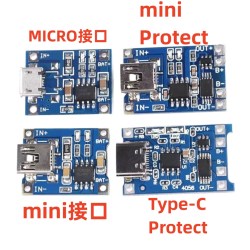
Other than that, you’ll want some Aliexpress-obtainable boards – TP4056 charger boards, and optionally a 5 V step-up if you’re going to be charging off of something other than USB.
Now you need a battery. You’ll want to pick one that has about 3.7 V nominal voltage, and about 4.2 V full charge voltage – which is most of them except stuff like LiFePO4, that we won’t talk about here. You can buy new or harvest them from other devices, Old 18650s from devices like laptops are fine as long as they don’t look suspicious, aren’t mechanically damaged, and you get them a holder – don’t solder to them. Pouch batteries are also fine, again, if they’re undamaged, healthy-looking, not overdischarged, and solder to them carefully if you must. You also might want to get a protection circuit to safeguard your battery – TP4056 boards I recommend tend to already have one included, you can harvest them from old devices otherwise, or just get them from Aliexpress. Also, if you’re reusing a smartphone cell, there likely will be a protection circuit present.
Last, look at your dev board – find its schematic if possible, too. Chances are, it’s in one of the three categories as far as powering boards goes – “needs 3.3 V”, “needs 3.3 V to 5 V”, or “needs 5 V”. The overview is that we’ll supply 5 V to the TP4056 charger module to charge up the battery, and depending on the dev board, we’ll need to take the battery’s output and condition it further. Here, our paths diverge.
Your Board Needs 3.3 V
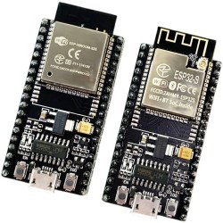
An ESP32, an ESP8266, and a Pi Pico, all have the same thing in common – they simply need 3.3 V for power, and you can provide this easily from a LiIon battery, so at its core, you only need a 3.3 V regulator. On many ESP32 and ESP8266 boards, there’s even a 1117 style regulator on the board already, but those tend to have a problem. The 1117 regulators are uniquely bad for LiIon use. Because of their high drop-out voltage, they fail to provide 3.3 V at as low as at 4 V input, so when the battery is at 50% capacity, they’re already cutting out. There are pin-compatible substitute LDO regulators that are very cheap and accessible – AP2111 and AP2114 are my favourites, so get a few of those. As for Pi Pico boards, or ESPs with small SOT23-5 package regulators, those tend to already be LiIon-compatible!
So we have a 5 V USB input, we have a LiIon battery that needs charging, and we need 3.3 V for the microcontroller. Wire the TP4056 board to the 5 V, and wire its output to the battery. One caveat exists – you can’t pull power from the battery while it’s being charged, that will mess with the LiIon charger chip algorithm! We solve this with three components – a resistor, a diode, and a small MOSFET, mixing the charger and the battery voltage in a way that the charger input is used for power whenever the charger is plugged in. This creates a power rail that goes from about 5 V, down to as low as the battery will go, which is about 3.5 V in practice. I refer to this three-component circuit as a “power path”, because that’s the how circuits for such purposes are usually known as!
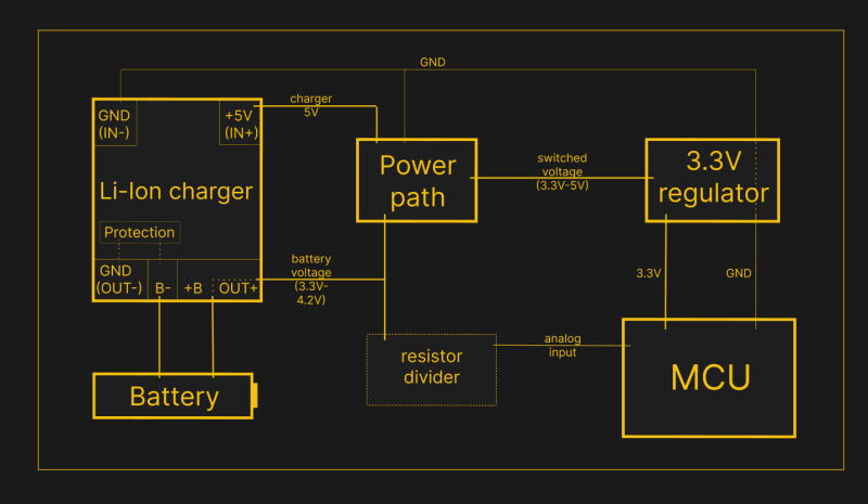
You can, of course, add this circuit to a development board – many Sparkfun and Adafruit boards do exactly this, and so do a lot of Eastern-designed devboards. Also, you can measure battery voltage through a resistor divider, as a very crude proxy for state of charge. For ESP32 and ESP8266 boards, dividing battery voltage down to 1 V is the best choice for measurement accuracy for their ADC peripherals, so, you can do something like 330 kΩ / 100 kΩ divider, and for 3.3 V friendly ADCs on a RP2040 or an ATMega, a 1:1 divider (i.e. 470 kΩ / 470 kΩ) will do just fine. Want part recommendations? We talked through those in the last article!
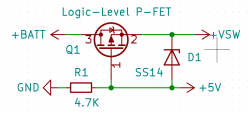 Oh, and, fun thing about the Pi Pico? Look at its schematic, and notice a fun thing – we have access to all the signals and components we need, and the necessary diode is already present on the Pi Pico board. To power a Pi Pico from a LiIon battery with all the benefits that our circuit brings, you only need a resistor, a FET, and a TP4056 board for charging.
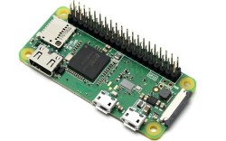
This is a seriously universal solution. It applies for a whole lot of devboards with so many different MCUs, you would easily lose track if I were to list them all. As much as these boards might be initially designed for 5 V, you don’t need to actually create 5 V unless you also need to also power things like servo motors or USB devices. But a Pi Zero, for instance, needs 5 V.
Your Board Needs 3 V to 5 V
There are a lot of Pi Zero battery HATs on the market, and most of them tend to use a powerbank-intended circuit to feed the Pi Zero with 5 V. This is quite inefficient because the Pi Zero itself doesn’t actually need 5 V. Internally, it feeds the 5 V input to its regulator to generate 3.3 V and 1.8 V that the chips actually need. Also, there’s a secret – you can feed that regulator with as low as 3.3 V, as it has 100% duty cycle mode that allows it to do pass-through. This results in the regulator having a wide input range, from low 3.3 V to 5 V. Remember our power path circuit? Yeah, you can just use that again.
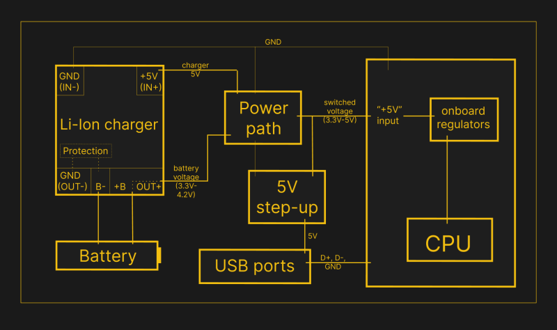
Here’s a very important consideration we shall solve! See those microUSB ports on the Pi Zero? They are directly connected to the regulator input, which in turn has a direct connection to the battery whenever a charger is not connected. Your task is to make sure you can’t accidentally plug anything into these ports anymore. Thankfully, not many people actually desire a MicroUSB port, much less a MicroUSB OTG port – solder your own USB-A or USB-C port to the GND/D+/D- testpoints on the bottom, and bring 5V from an additional step-up regulator.
 If you plan to use the HDMI port, not all HDMI devices will be compatible with receiving 3.3 V on HDMI’s dedicated power rail, so if you encounter problems, you might want to supply your 5 V to the HDMI 5 V pin too – it has a diode you can comfortably solder a wire onto. Those are about all the problems with this method, and in return, you get a seriously increased battery life – I can run a Pi Zero with a few peripherals for over 20 hours from a 5000 mAh LiIon cell.
But if you need the 5 V, how do you find a 5 V step-up? Usually, search through the same place you got your TP4056 boards from. LM2956 regulators will be too bulky if all you want is to power a USB device or two, and the three-pin IC ones will be too underpowered, but there are a lot of regulators in the middle that will be fine generating 5 V at 500 mA for anything you need. I much prefer these because they even appear to work fine when powered from 5 V; it’s been about 7 years since I started using these, so, you might just find a better option too. Also, many USB devices can be powered from 3.3 V, just that it’s quite a gamble on which ones do.
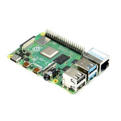
This, too, applies to more than just the Pi Zero. For instance, I’ve recently taken a look at the Banana Pi M4 Zero schematic while doing my research, and its regulator seems to be fully compatible with this powering method, too – save for the SY8089 regulator powering the WiFi module. Full-sized Pi boards, though, won’t work well with this method – with those, you will want to straight up power your board from a 5 V step-up or step-down.
Your Board Absolutely Needs 5 V
If you’re sure your board truly needs 5 V, you should indeed provide it with that. This is where the circuit tends to get simple, because there are a lot of ICs for this task – you have to do the same thing that a powerbank does, so for a lot of purposes, you can reuse a powerbank circuit. You will find these circuits on boards inappropriate and appropriate alike – for instance.
One of the problems with the powerbank IC approach is that many of these chips will shut down their 5 V output whenever a charger is plugged in. For that, you could semi-easily build a FET-based switch that passes charger voltage through whenever the charger is plugged in, and, perhaps, disconnect the IC’s output too while at it. Want an open-source design example you can modify and manufacture? Here you go. Got a USB-C powerbank that has combined USB-C input and output? You can likely use the simplest possible USB-C dock with charging passthrough that provides you with a USB-A or USB-C output port.
The 5 V approach is simple, and the main problem with it is that it’s wasteful. If you’re powering a Pi Zero, this kind of circuit will step the battery 3 V to 4 V up to 5 V only to have the Pi Zero step it back down to 3.3 V, which makes you waste a noticeable amount of power on regulator loss instead of powering your CPU for more hours. In a pinch, you can always rely on the straightforward powerbank-style boards, but if you don’t actually need 5 V, the decreased runtime will make you sad, which is why you should know about the circuits above.
Reference Design To Last You Until Next Time
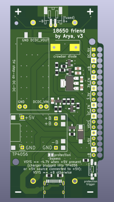
Last but not least, here’s a reference design for KiCad for all your LiIon needs. I’ve developed a power-your-portable-devices helper PCB that can help you handle a wide range of LiIon batteries you might work with, whether it’s pouch cells, or 18650s in holders SMD and THT alike. This board has a ton of quality-of-life features! There’s the power path, TP4056 and 5 V DC-DC footprints with FET control for the DC-DC, JST-SH 2-pin connector for pouch cells (Adafruit polarity), fuses for two 18650 cells you can put on it, an extra USB-C port for charging wired to the TP4056, wiring holes for connecting wires to the board in a mechanically stable way, reverse polarity protection and even per-cell reverse polarity alarm LEDs, separate 3.3V LDO with FET control that’s compatible with both SOT0223 and SOT23-5 LDOs, and even a protection trigger button in case the protection circuit gets stuck in the shut-off state like I’ve described. Plus, I’ve recently added a few mounting holes on the corners, improved wrong polarity silk markings for LEDs, and D-/D+ testpoints for the onboard USB-C port – after all, I’ll need to order a new batch of these boards soon!
I’ve originally developed this board for my own use on hardware hackathons, where I noticed myself always having to roll a small-scale solution for powering whatever gadget I was hacking away at – saving a few hours during a hackathon tends to result in great outcomes. Over the years, this design has powered multiple portable projects of mine, including designs I’ve used for years, and I’ve even used it to trigger small-scale explosives a couple of times – in Minecraft, of course. The design is fully open, so you can remix it, steal footprints and symbols from it, manufacture a small batch, it’s up to you.
Now, what if you need more, like 12 V? At some point, step-ups for such voltage will become inefficient, and you might just want to connect LiIon batteries in series, like many higher-power devices do. This does require more care from you, though, which is why so far, we’ve only talked about single-series configurations. Let’s devote the next article to putting multiple cells in series, so you know what it takes to treat batteries safely while getting a comfortably high voltage for any circuit you might have in mind.
Recommend
About Joyk
Aggregate valuable and interesting links.
Joyk means Joy of geeK