

Adam's Vintage Computer Restorations
source link: https://retrorepairsandrefurbs.com/2022/09/06/1956-philips-353a-bakelite-vacuum-tube-radio-repair-restoration/
Go to the source link to view the article. You can view the picture content, updated content and better typesetting reading experience. If the link is broken, please click the button below to view the snapshot at that time.
1956 Philips 353A Bakelite Vacuum Tube Radio Repair & Restoration

A few months ago I bought my first ever vacuum tube radio, a 1956 Philips 353A bakelite AM/FM set, which is (currently) the oldest item in my collection. I’ve been wanting to get into vintage radio restoration for some time now (after watching YouTube channels such as the excellent Mr Carlson’s Lab), as I find the electronics fascinating.
I bought it in unknown condition from an antique shop in Kirkby Stephen for £30.00 – it was in pretty rough physical shape, and the external antenna connector had been cut off.

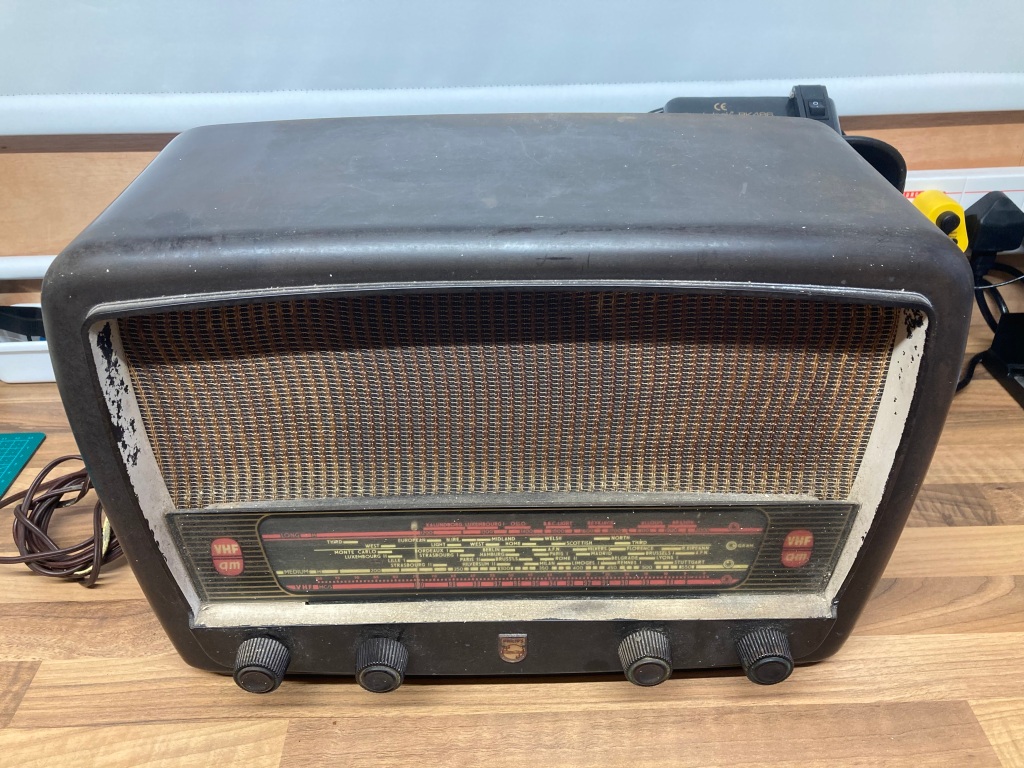
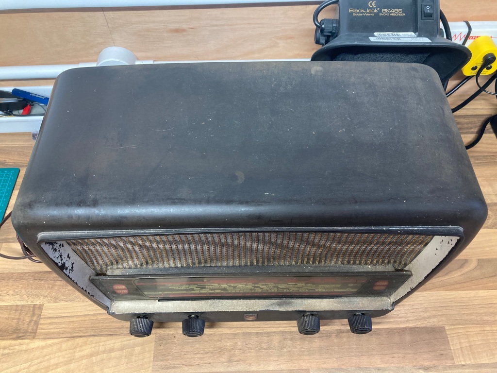
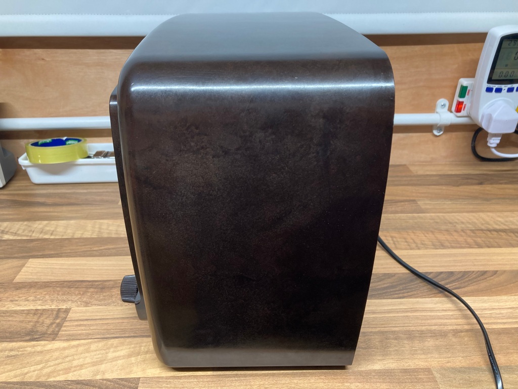
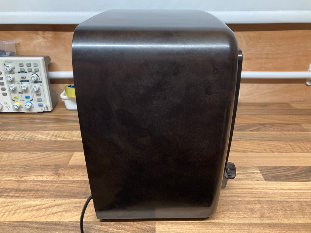
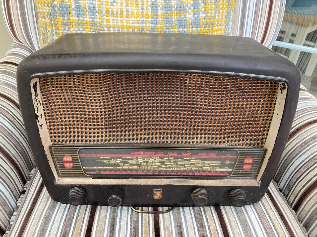
 Philips 353A vacuum tube radio before restoration.
The 353A is a reasonably complex mains-powered seven-tube superheterodyne radio receiver, with a channel switch and internal antenna, and connectors for an external antenna and a direct audio input (“gramophone pickup”).
If you’re interested in how “superhet” radios work, “Transistor Superhet Receivers” by none-other than Sir Clive Sinclair himself is an excellent book.
Radio Disassembly & Inspection
Electronics of this vintage usually contain components that frequently deteriorate or fail with age, and can (at best) cause damage to the tubes and other circuitry if left unchecked – radios from this era therefore need to be inspected and serviced as required before being powered up directly from a mains supply (without current limitation).
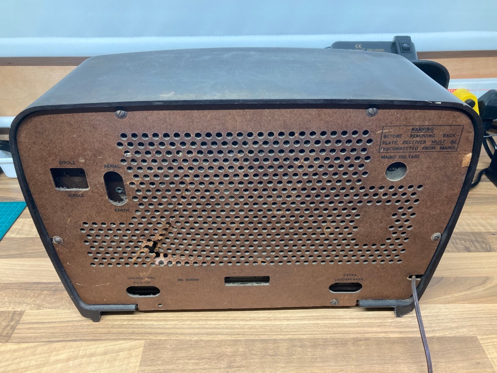
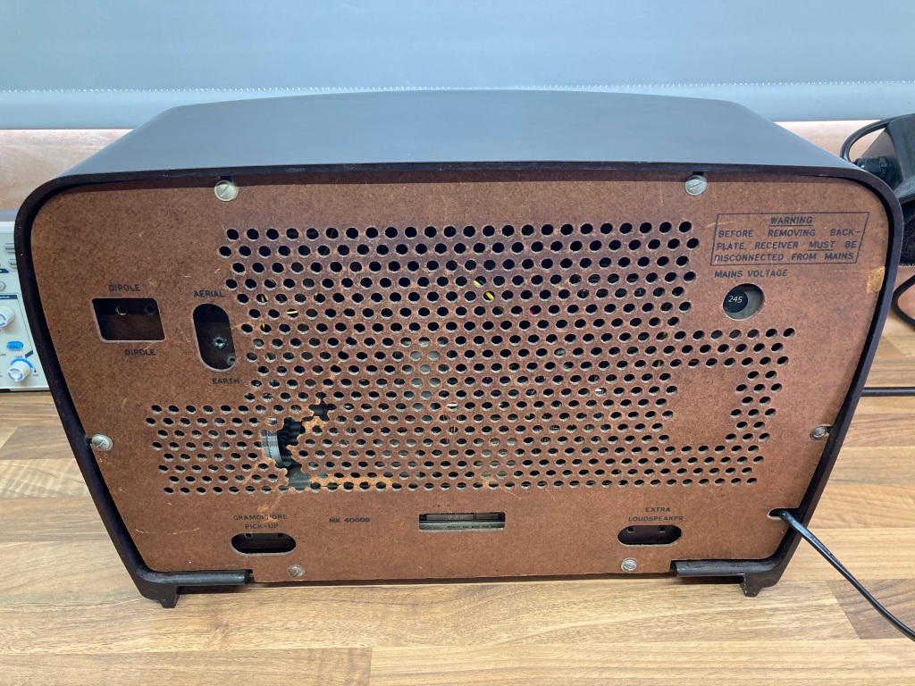
The 353A is quite an easy radio to disassemble, and only six flat-head screws hold the rear cover on – some sets of this era contain asbestos (especially the rear covers) so must be handled with extreme care, however as far as I am aware this radio does not.
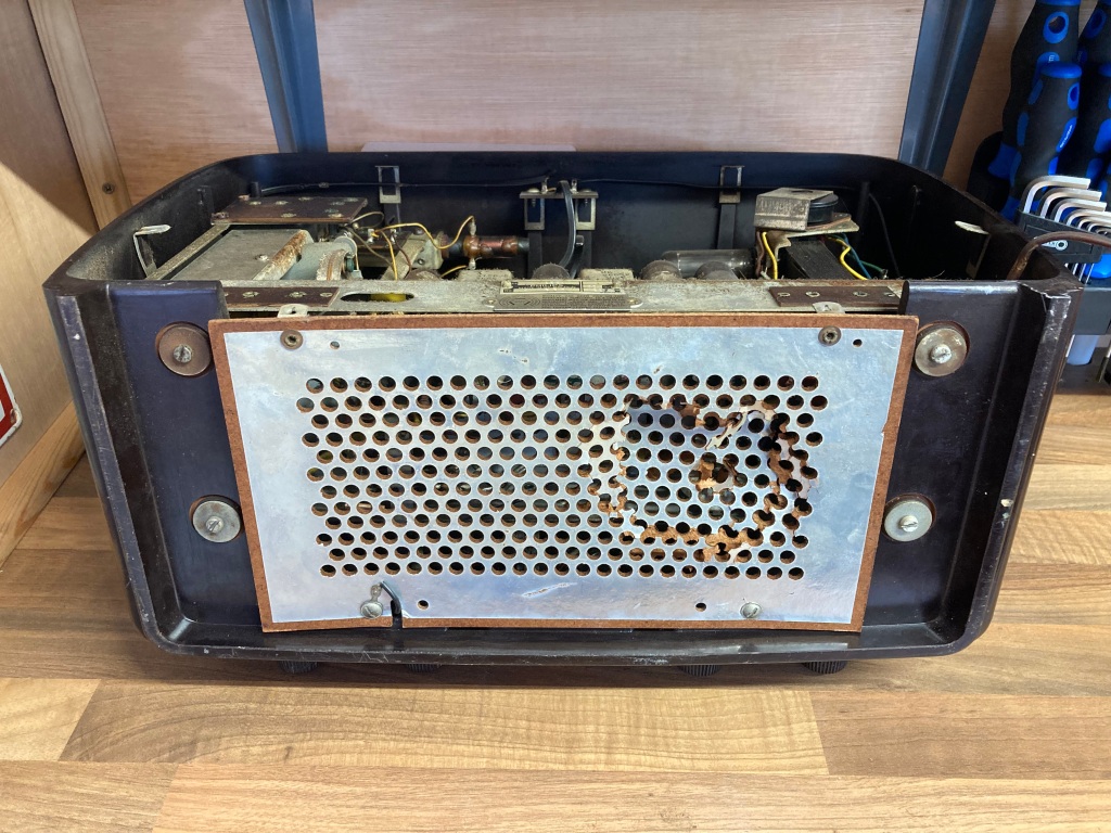
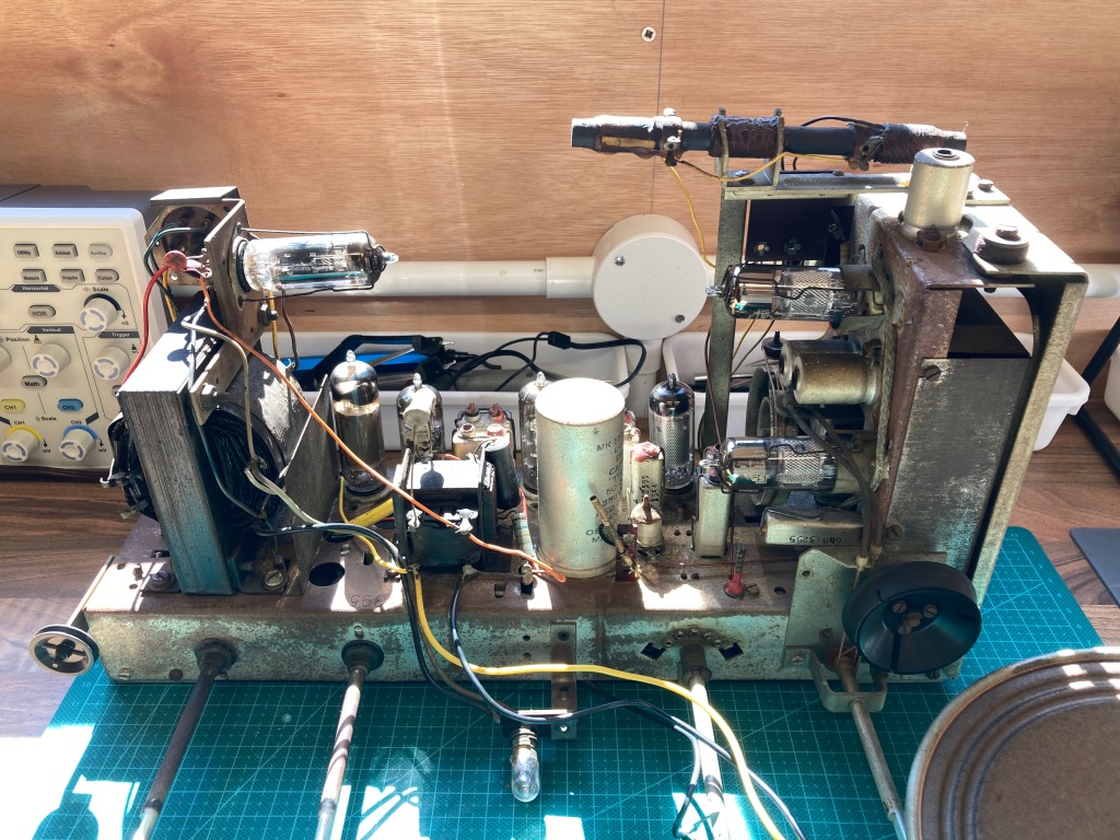
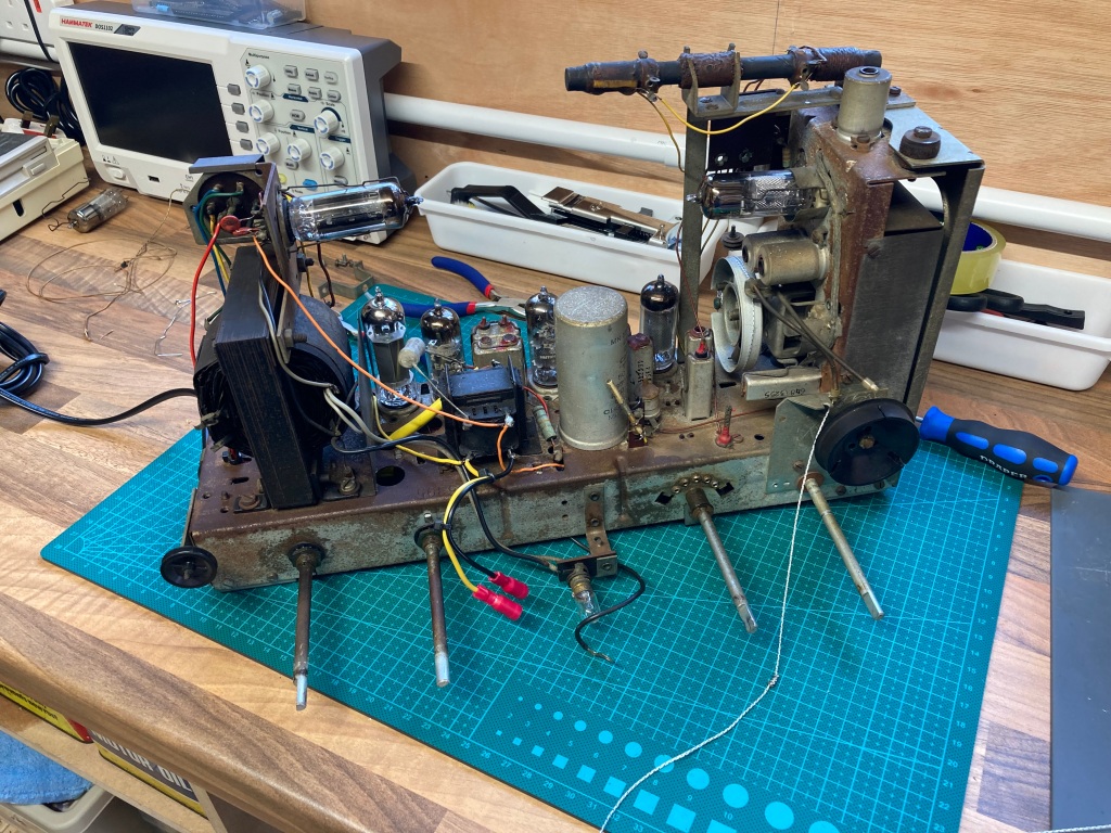
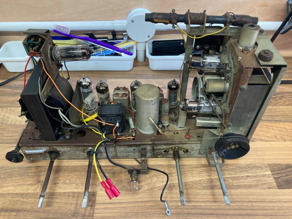
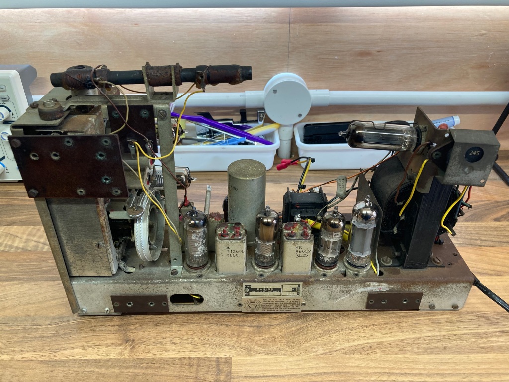
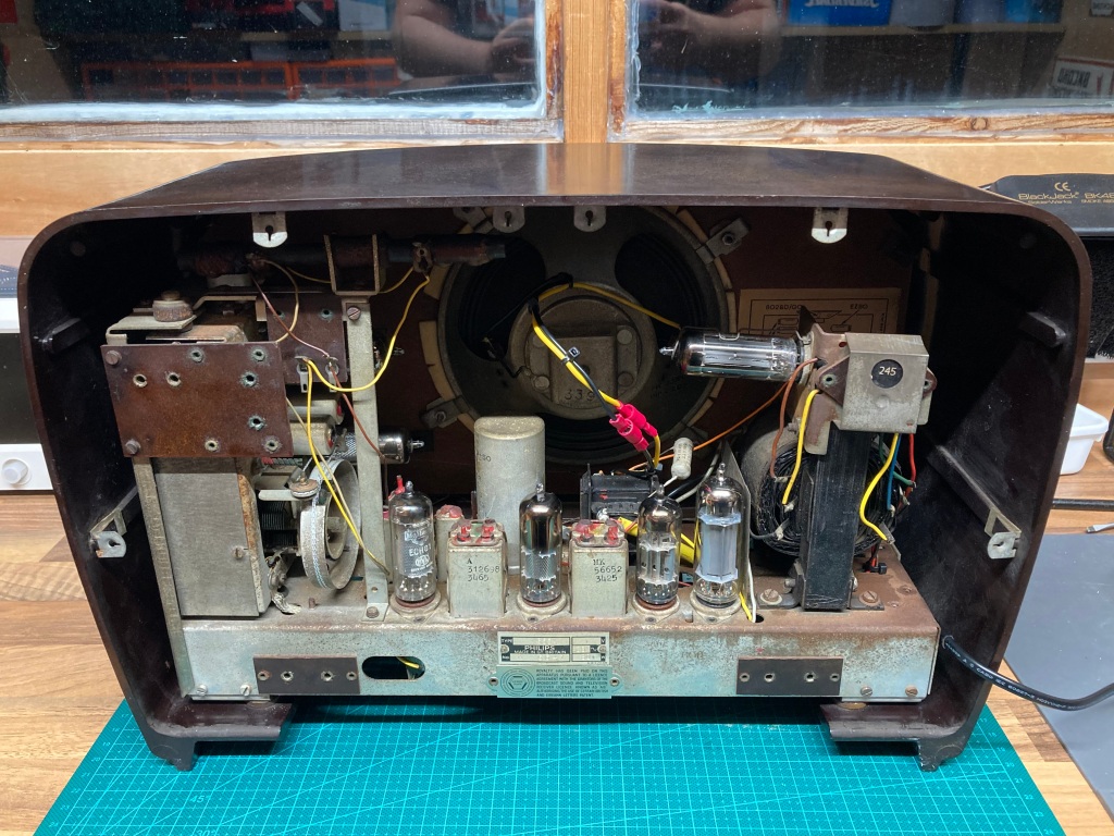
With the rear cover removed, you get your first proper look at the chassis. In this case, it was very baked-out and dusty, so this was obviously a well-used set – however, all of the tubes were present and everything seemed to be original.
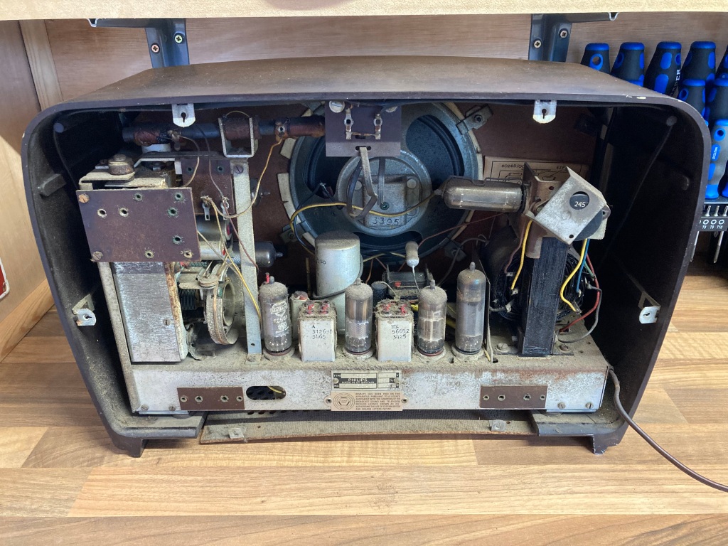
Rear cover removed, and first look at the rear of the chassis.
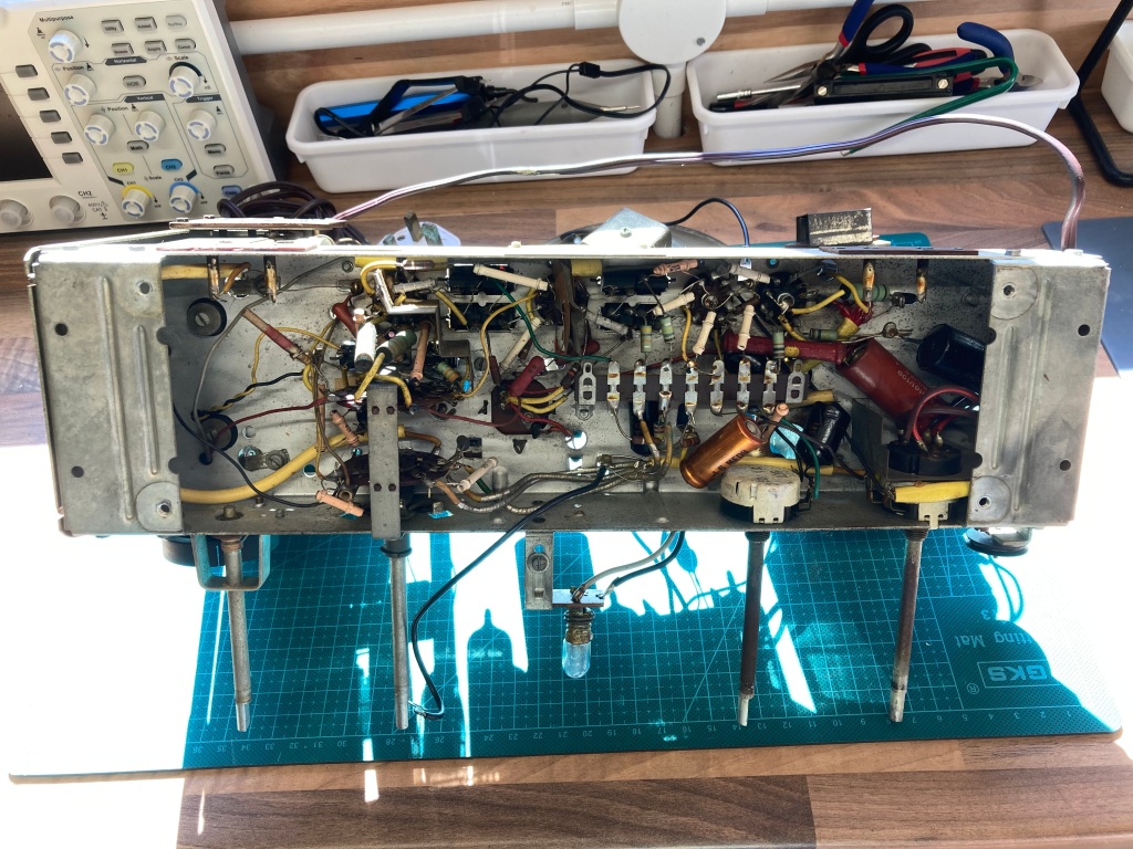
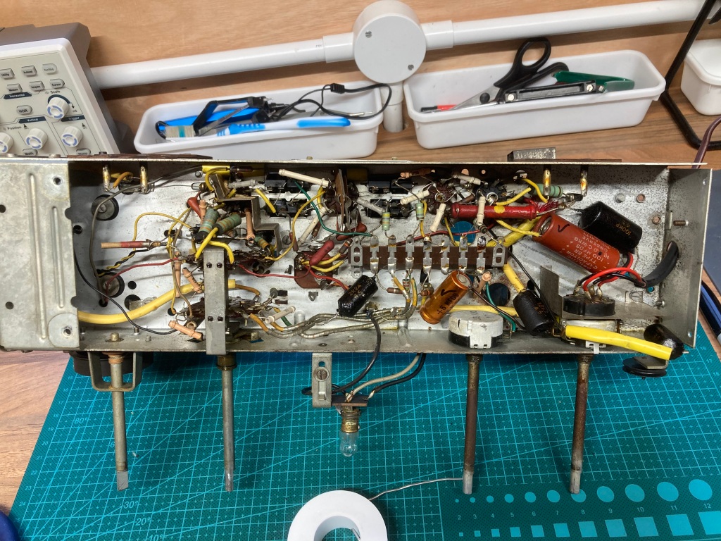
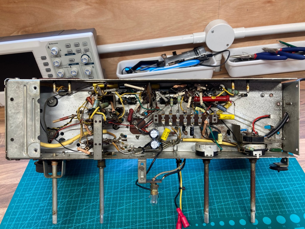
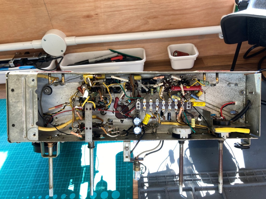
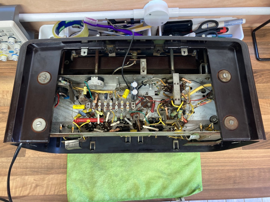
The bottom cover is only held on with two flat-head screws – with this removed, the point-to-point wiring in the underside of the chassis is revealed. This is what circuits used to look like before printed circuit boards were commonplace!
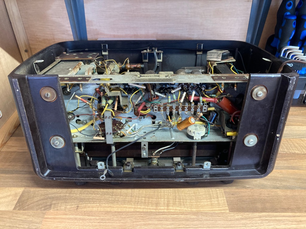
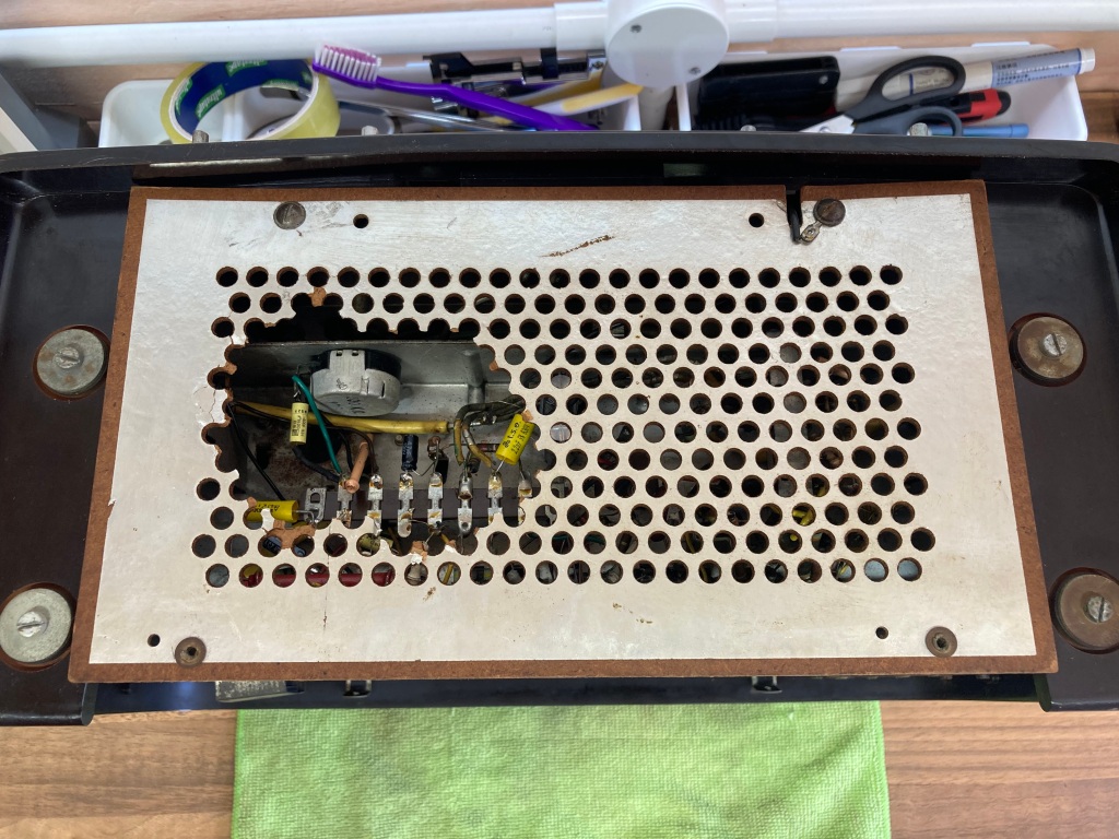
Bottom cover removed, and first look at the underside of the chassis.
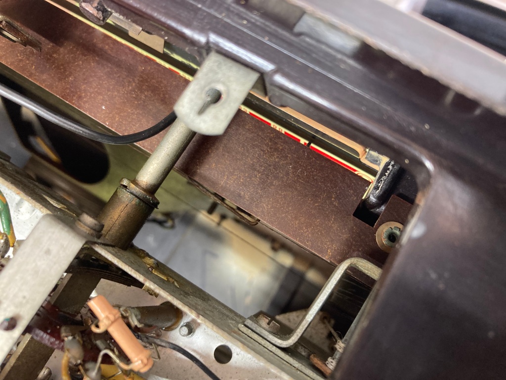
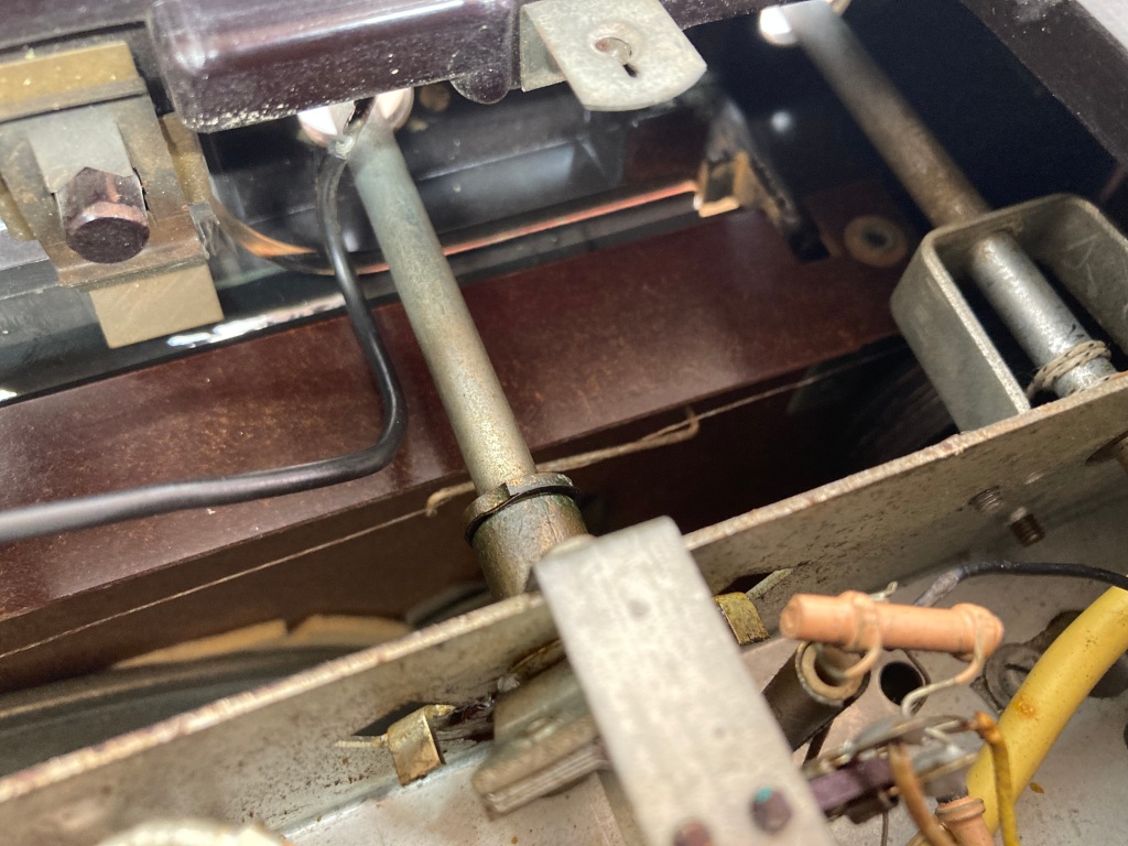
The radio chassis is held in place with four flat-head screws with rubber spacers; before the chassis can be removed from the case, the dial pointer should be removed from the dial string, which is simply raveled around it.
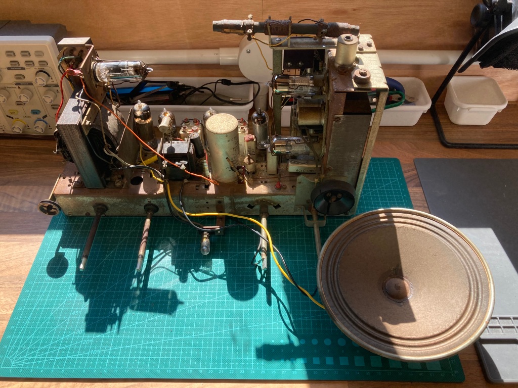
Chassis removed from the radio case.
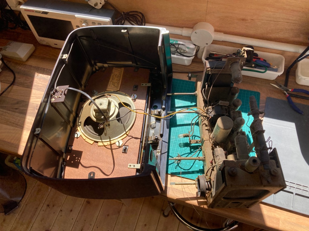
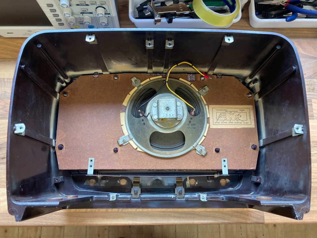
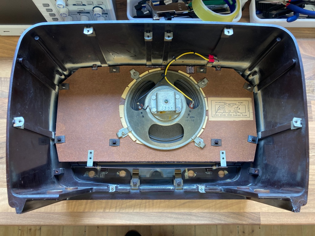
The front speaker is permanently wired in this radio, so I removed it from the from the case to allow easy access to the chassis – it’s held in place with four nuts and holding bars.
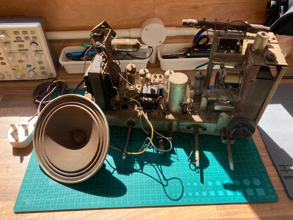
Chassis and speaker removed from the radio case.
The internals were very dirty and obviously well-used, but everything seemed to be intact and complete. I therefore planned out the restoration as follows:
- Chassis cleaning and inspection.
- Electrolytic and paper/wax capacitor replacement.
- Mains cable replacement.
- Tube inspection and replacement.
- Tuning cord replacement.
- Case cleaning and polishing.
- Front fabric replacement.
Chassis Cleaning and Inspection
I took this opportunity to clean up the radio chassis, in order to get a good look at everything that needed to be worked on.
I blew the worst of the dust and muck off with compressed air; then, I cleaned the chassis, components, and tubes using a general degreaser and a microfibre cloth, carefully removing the tubes to do so.
I cleaned all of the tube sockets and controls with contact cleaner; I found that the band selection switch was pretty well seized up, so I soaked the contacts with standard WD-40 until they freed up, then worked the switch through all of its positions to clean them up.
Radio chassis following the initial clean-up.
Electrolytic Capacitor Replacement
Aluminium electrolytic capacitors are commonly used for filtering, smoothing, and decoupling in both high- and low-voltage electronics. They typically comprise aluminium windings which are coated with a liquid electrolyte, which can dry out over time (negatively affecting the performance of the capacitor, often causing them to fail dead-short), or leak out and cause corrosion to the PCB and surrounding components.
The 353A is a 1950s radio set, and as such was made with 1950s electrolytic capacitors – these are far inferior to modern equivalents, and coupled with their advanced age, they should ideally be replaced before attempting power-on.

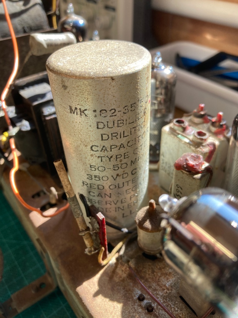
Two of the electrolytic capacitors (large cans).
More electrolytic capacitors.
There are only four electrolytic capacitors in the 353A:
- C1: 50uF 350Vdc electrolytic (inside the large Dubilier metal can).
- C2: 50uF 350Vdc electrolytic (inside the large Dubilier metal can).
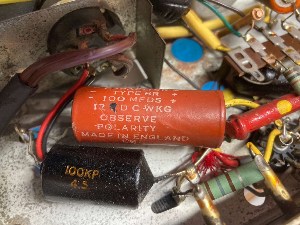
- C3: 100uF 12Vdc electrolytic (large red Dubilier capacitor).
- C4: 5uF 75Vdc electrolytic (large orange capacitor).
The two electrolytics wired point-to-point are easy enough to remove and replace – components wired point-to-point like this typically have their leads wrapped around one another for mechanical strength, so this needs to be unpicked while desoldering.
I removed and replaced these one-by-one, making sure to keep their leads as short as possible, using a 100uF 25V axial part in place of the large red Dubilier capacitor, and a 4.7uF 100V radial part in place of the large orange capacitor.
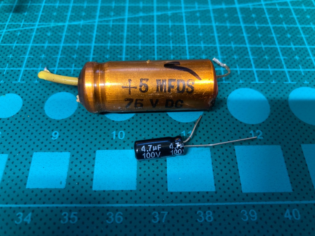
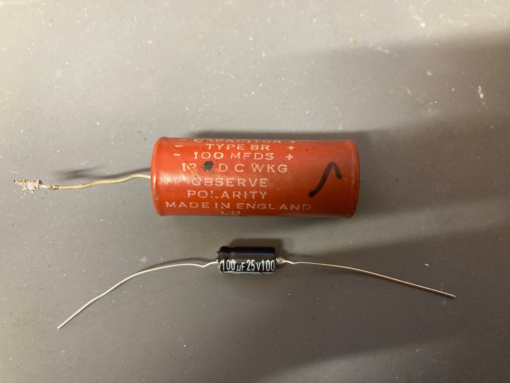
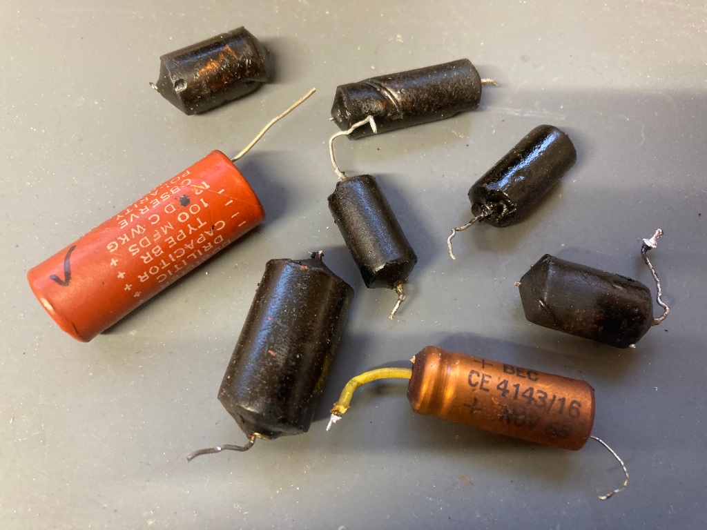
Old versus new electrolytic capacitors.
The new parts are significantly physically smaller than the originals, which just goes to show how far capacitor technology has advanced over the past 70 years.
It’s also difficult to get exact matching replacements for some of the values – for example, I substituted a standard 4.7uF capacitor for the non-standard 5uF capacitor. This kind of substitution should be okay for electrolytics, as they typically have a wide manufacturing tolerance anyway (up to 20%). It is important to use a capacitor with the same or higher voltage rating as the original.
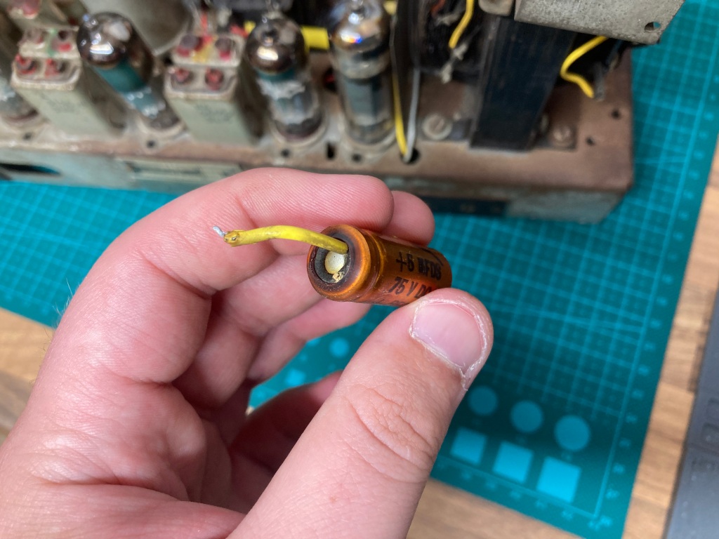
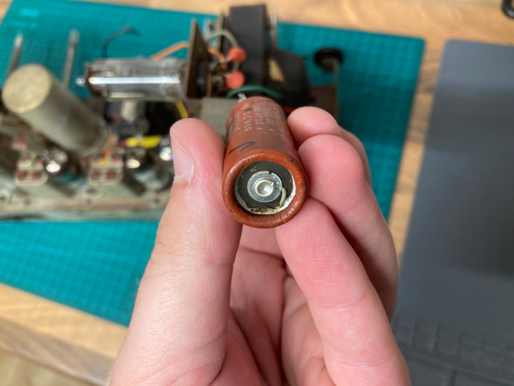
Capacitor damage.
It was definitely worth replacing these, as the red capacitor showed signs of physical leakage, and the orange capacitor showed signs of heat damage.
As for the two capacitors in the large can, there are several schools of thought on how to replace these: some people remove the capacitors inside the original can and re-stuff it using new capacitors; some people install new capacitors, and remove the can entirely; some people remove the old can from circuit, and install new capacitors.
My preferred method is to remove the can from circuit, and install new capacitors – this means that the radio chassis maintains its stock look from the top, but is easy to service in future. Either way, it is extremely important to remove the original capacitors from the circuit (not just solder the new capacitors across them), as the originals can become physically leaky and affect performance, or fail dead-short and cause radio damage.
Typically, the outside of the can is connected to the negative side of the capacitors inside it, and there is a terminal for the positive side of each capacitor on the bottom of the can.
Replacement mains filter capacitors fitted.
In this case, I installed two 47uF 400V radial parts in the underside of the chassis, held in place with some cable ties – I used one of the can terminals to steady the positive connections to one of the capacitors, but I made sure that this was electrically isolated.
Electrolytic capacitors replaced.
Electrolytic capacitors are polarised, meaning that they must be installed in the correct orientation, otherwise bad things usually happen. It is therefore important to take particular care to ensure that the value, voltage rating, and orientation of the new capacitor are correct – this is more difficult with point-to-point wiring as the correct connection points aren’t obvious and the polarities aren’t marked, so it’s important to take plenty of “before” pictures to refer back to later on.
The Philips 353A has a very useful service manual, which includes a parts list and a chassis layout, which can be very helpful during recapping.
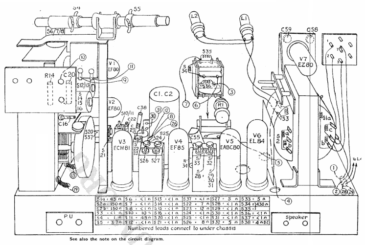
Upper chassis parts layout (image credit: RadioMuseum.org).
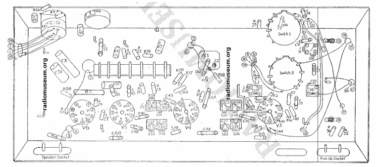
Lower chassis parts layout (image credit: RadioMuseum.org).
Paper/Wax Capacitor Replacement
The 353A also uses paper/wax capacitors – these antique capacitors are literally made from rolled-up paper and covered in wax, and like the electrolytic capacitors are also prone to failure from advanced age, including electrical leakage or opens/shorts.
These are far inferior to modern equivalents – most notably polypropylene, polyester film, and metallised film capacitors (ceramic capacitors are micro-phonic, so are not suitable for use in these circuits) – and like the electrolytics should ideally be replaced before attempting power-on.
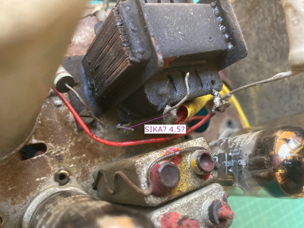
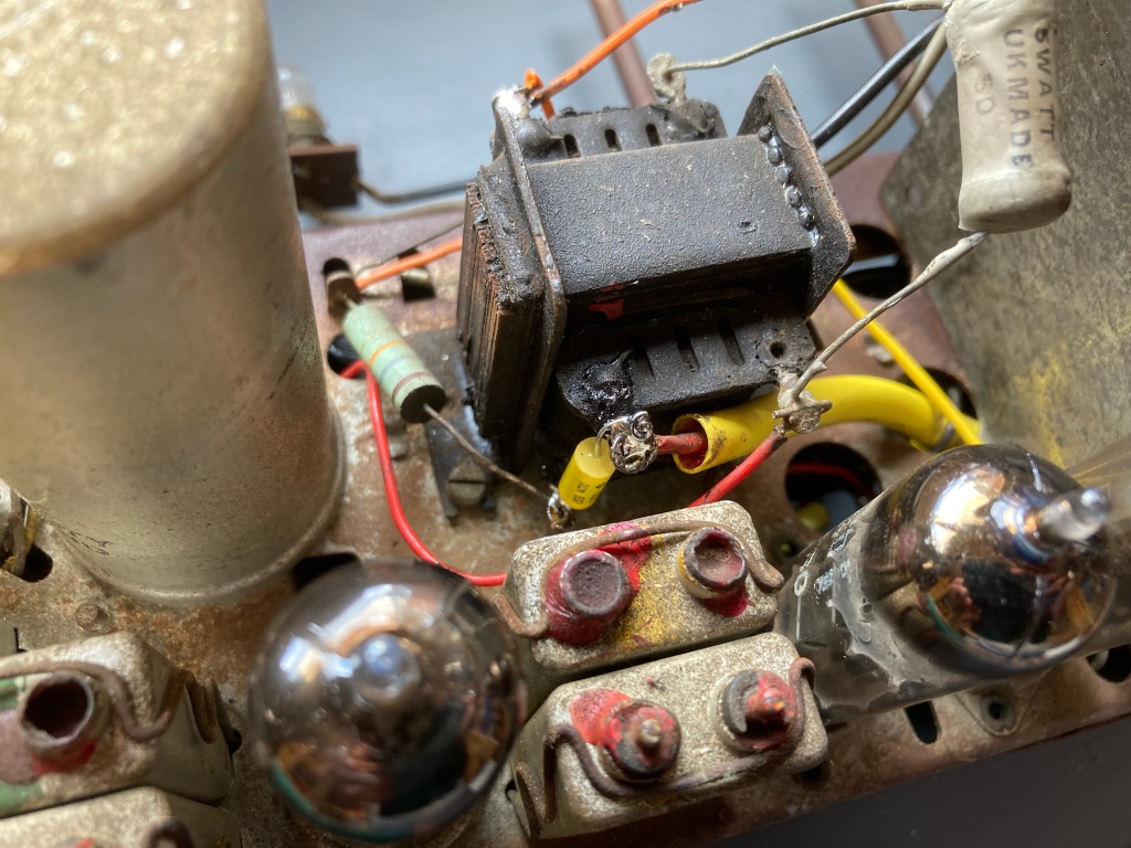
Four of the paper/wax capacitors (large dark brown cylinders with yellow markings).
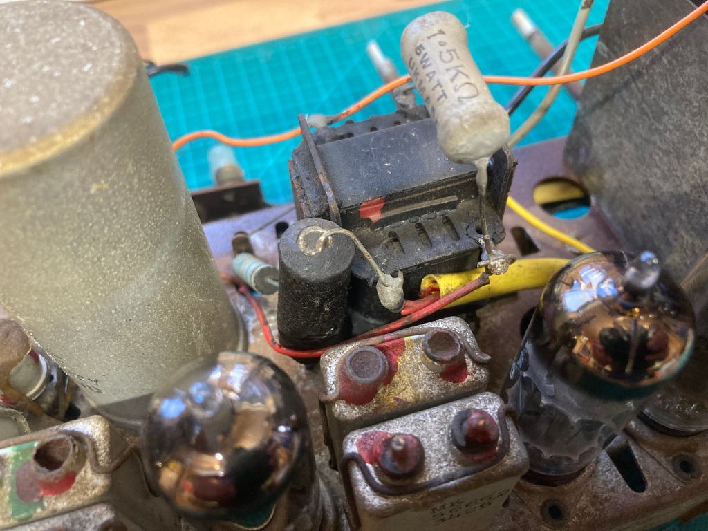
All of the paper/wax capacitors visible, including the one across the audio output transformer.
There are six paper/wax capacitors in the 353A:
- C47 (2K2A 4.5): 2,200pF (10%) (400V) – 2.2nF 630V Polypropylene Axial
- C49 (L8K2A 4.5): 8,200pF (10%) (1000V?) – 8.2nF 630V Polyester Film
- C51 (100KP 4.5): 0.1uF 400V – 100nF 630V Polypropylene Axial
- C52 (15KP 4.5): 15,000pF (400V) – 15nF 400V Polypropylene Axial
- C54 (15KA 4.5): 15,000pF (400V) – 15nF 400V Polypropylene Axial
- C55 (S1KA 4.5): 1,000pF (1000V) – 1nF 630V Polyproplyene Axial
The paper/wax capacitors are wired point-to-point and are easy enough to remove and replace – components wired point-to-point like this typically have their leads wrapped around one another for mechanical strength, so this needs to be unpicked while desoldering.
I removed and replaced these one-by-one, making sure to keep their leads as short as possible, using the parts listed above. I found it helpful to make annotations on some of my “before” pictures to ensure that the new capacitors were installed correctly.
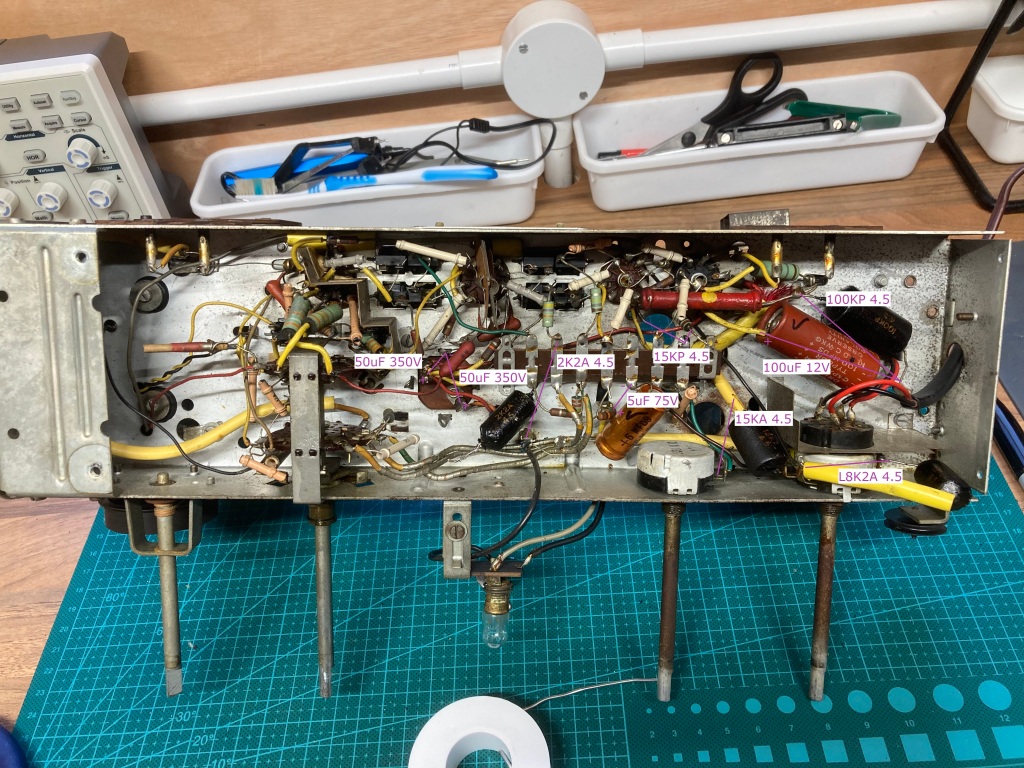
“Before” photos annotated with capacitor information.
Again, the 353A service manual was very helpful during recapping, as it includes a parts list and a chassis layout.
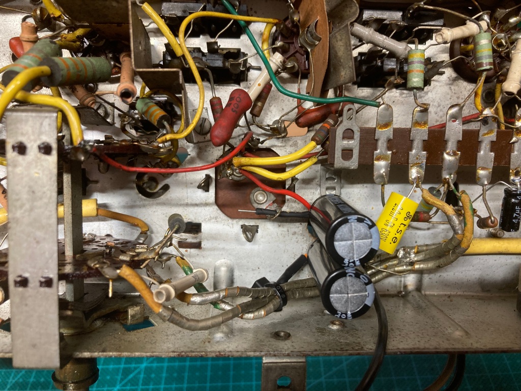
Replacement capacitors installed.
Original capacitors removed.
Mains Cable Replacement
An important safety consideration when refurbishing vintage radios is the mains cable – the original one on the 353A was in poor condition, so I decided to replace it with a modern moulded cable with 1A fused UK plug (in this case, I just bought a 2m figure-eight lead and cut the end off).
The mains cable is held in place with a strain relief, attached by a single screw – with this removed, I desoldered the original cable from the power switch terminals, taking care to note the polarity of the live and neutral connections. Installing the new cable was then just the reverse of removing the original.
Replacement mains cable installed.
Tube Inspection & Replacement
Before trying out the radio, I wanted to inspect the vacuum tubes for any obvious issues. All of them seemed OK visually except for the audio output tube (EL84), which was an original Mullard part – audio output tubes typically run very hot (150C+) and have a hard life, and this one didn’t look any different.
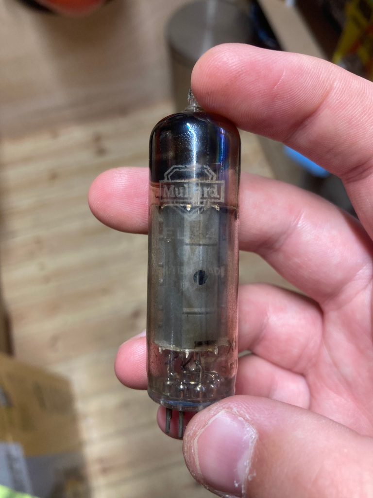
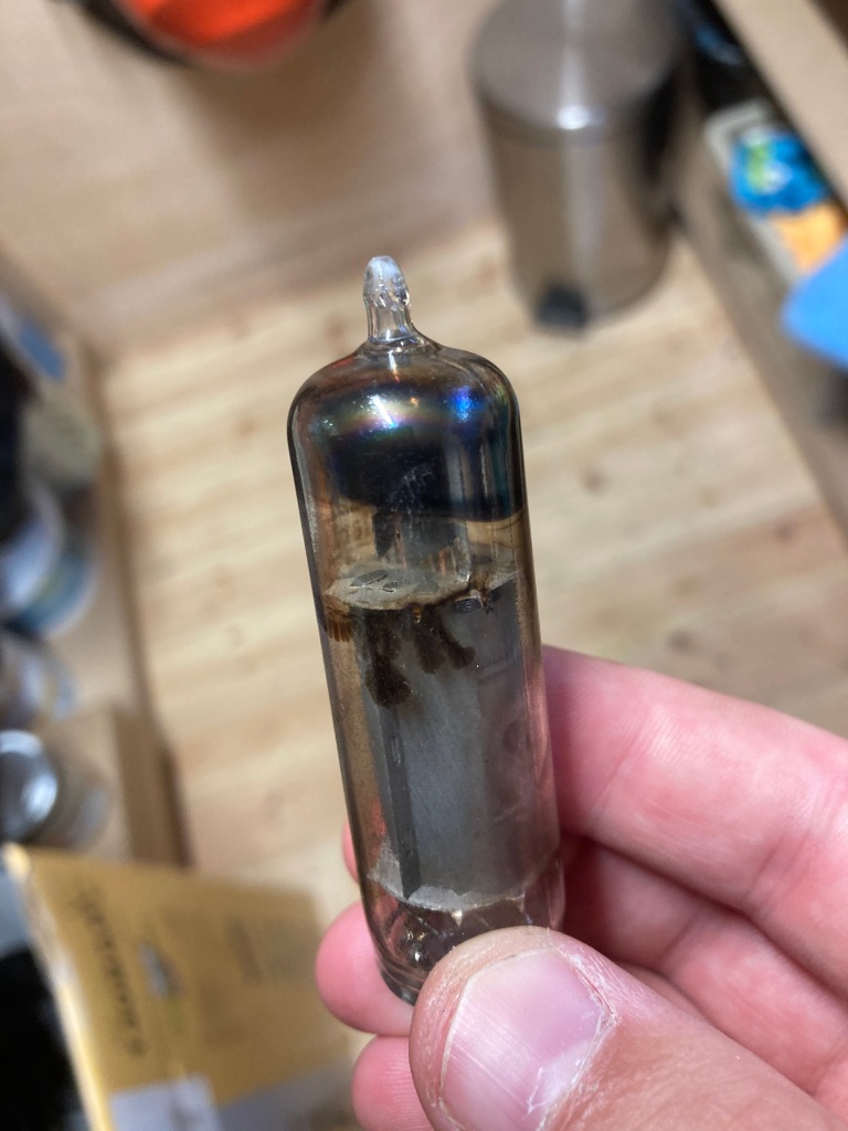
Original audio output tube.
I decided to replace it out of caution using a new-old-stock Langrex EL84 tube.
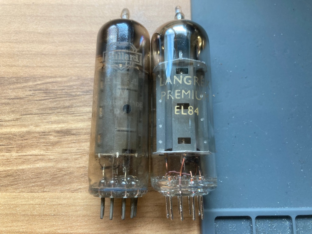
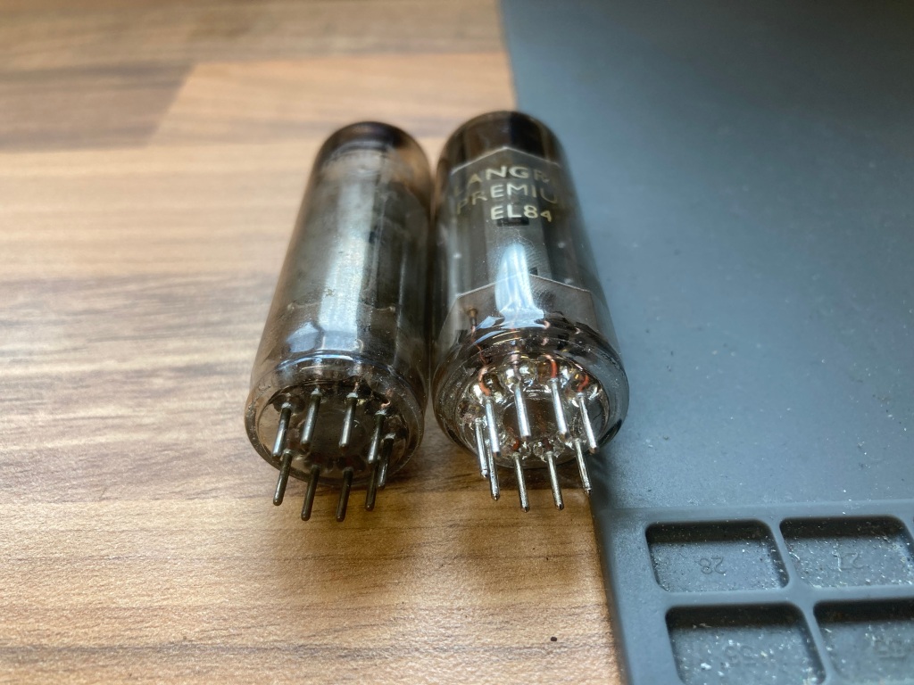
New audio output tube versus the orignal.
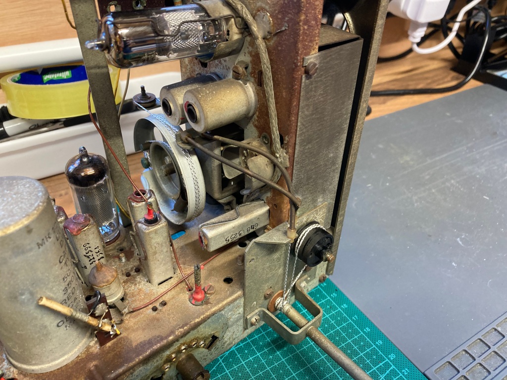
Tuning Cord Replacement
Whilst cleaning and testing the tuning control, the original tuning cord (which translates the rotary movement of the tuning control into the rotary movement of the tuning capacitor) snapped – the cord was pretty baked and very brittle, so this was only a matter of time. As such, I decided to replace it using some new-old-stock 0.6mm dial cord.
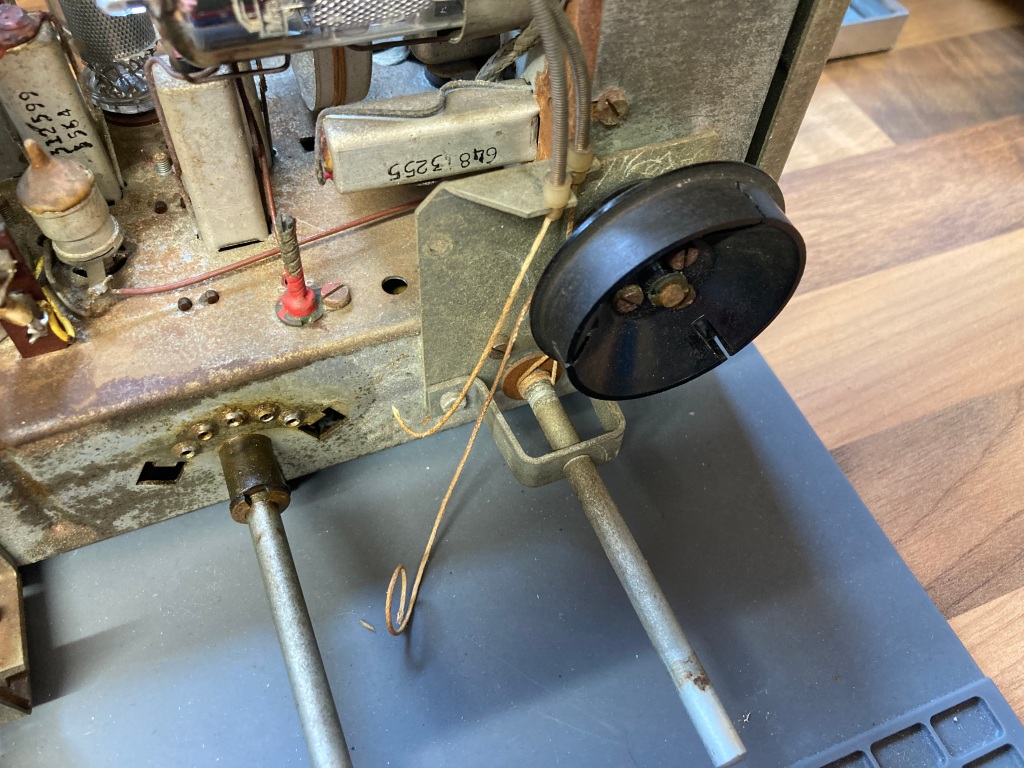
Snapped tuning cord.
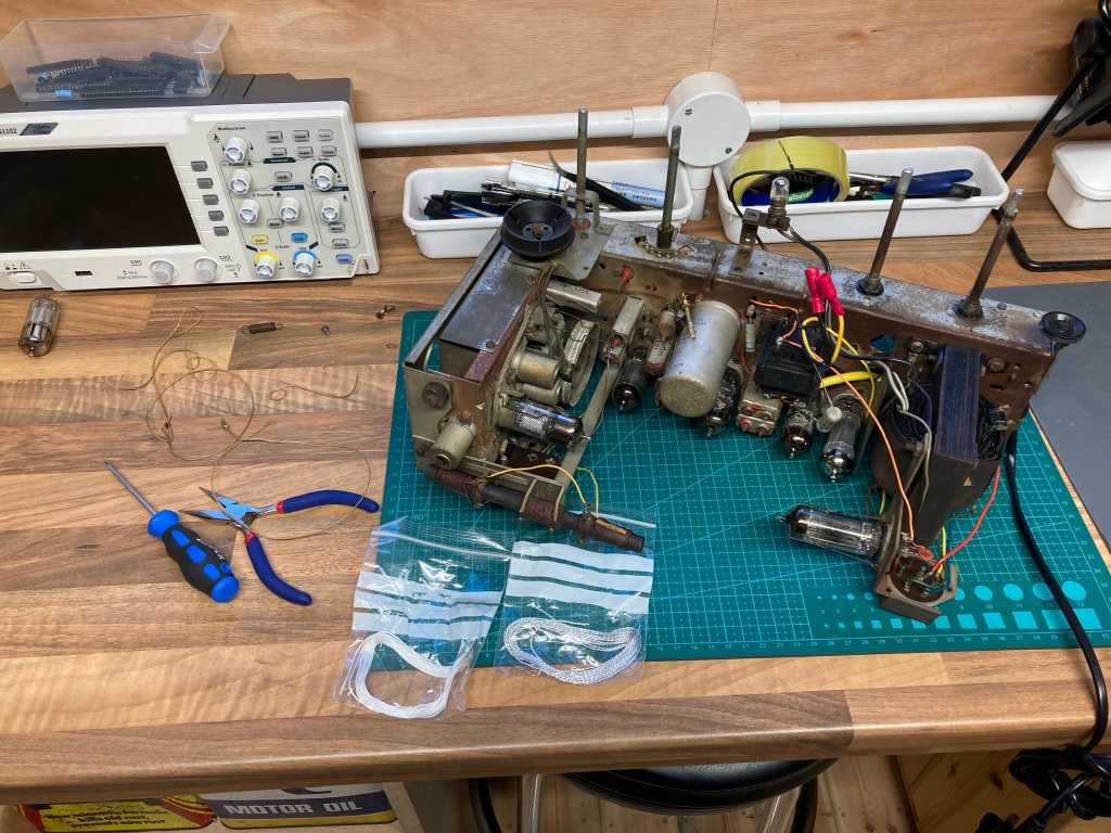
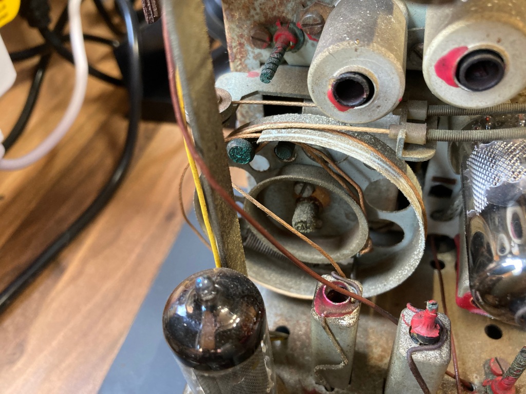
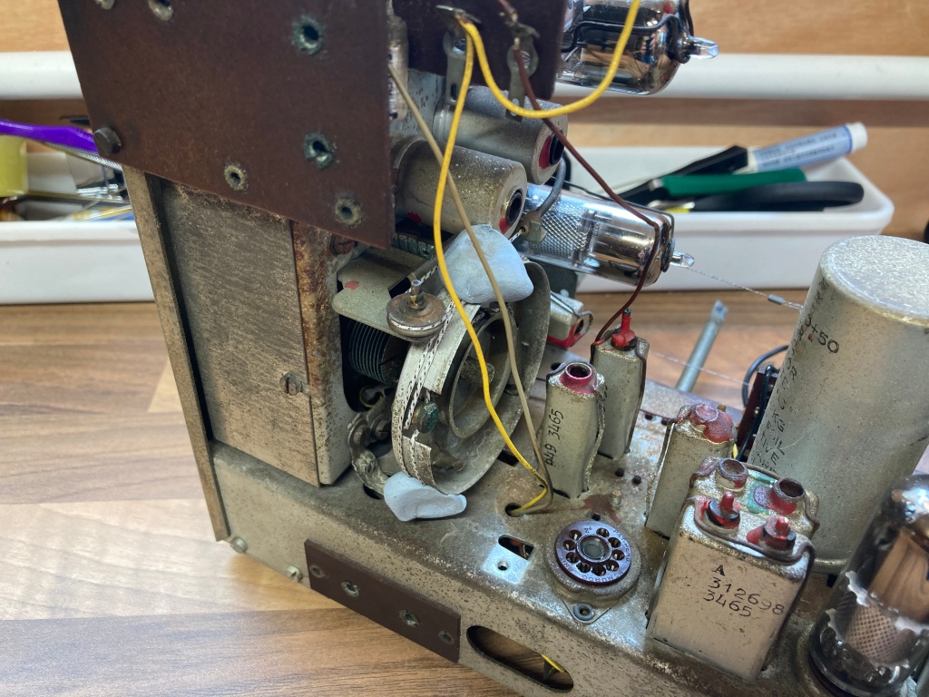
Installing the new cord.
This is a fiddly and frustrating process that takes a long time, especially if it’s your first time trying it – however, the procedure is documented thoroughly in the 353A service manual, including the lengths of cord, location of centre mark, and how to fit the tuning cord around the tuning control and tuning capacitor.
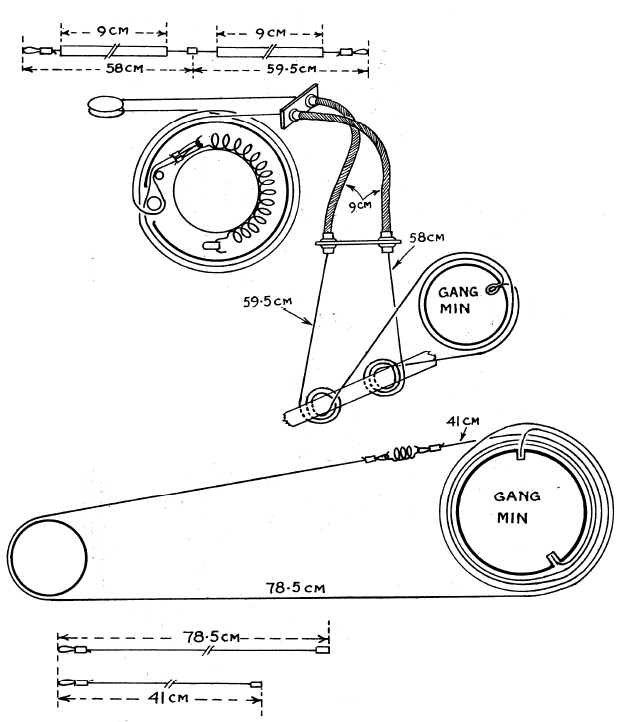
Tuning cord replacement information (image credit: RadioMuseum.org).
The cord requires a centre grip and a hook at each end, which I swapped out from the original snapped tuning cord.
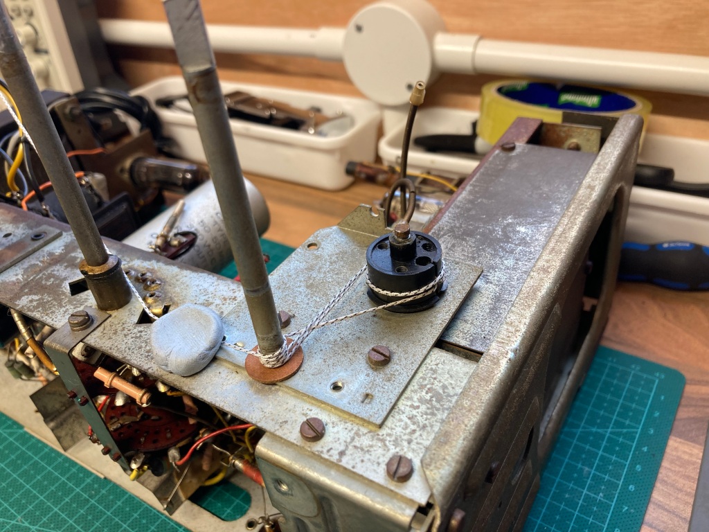
 Tuning control and the new cord.
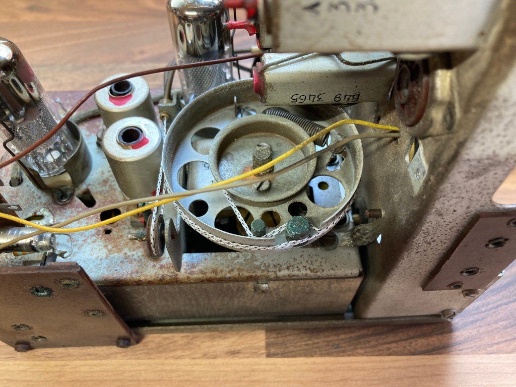
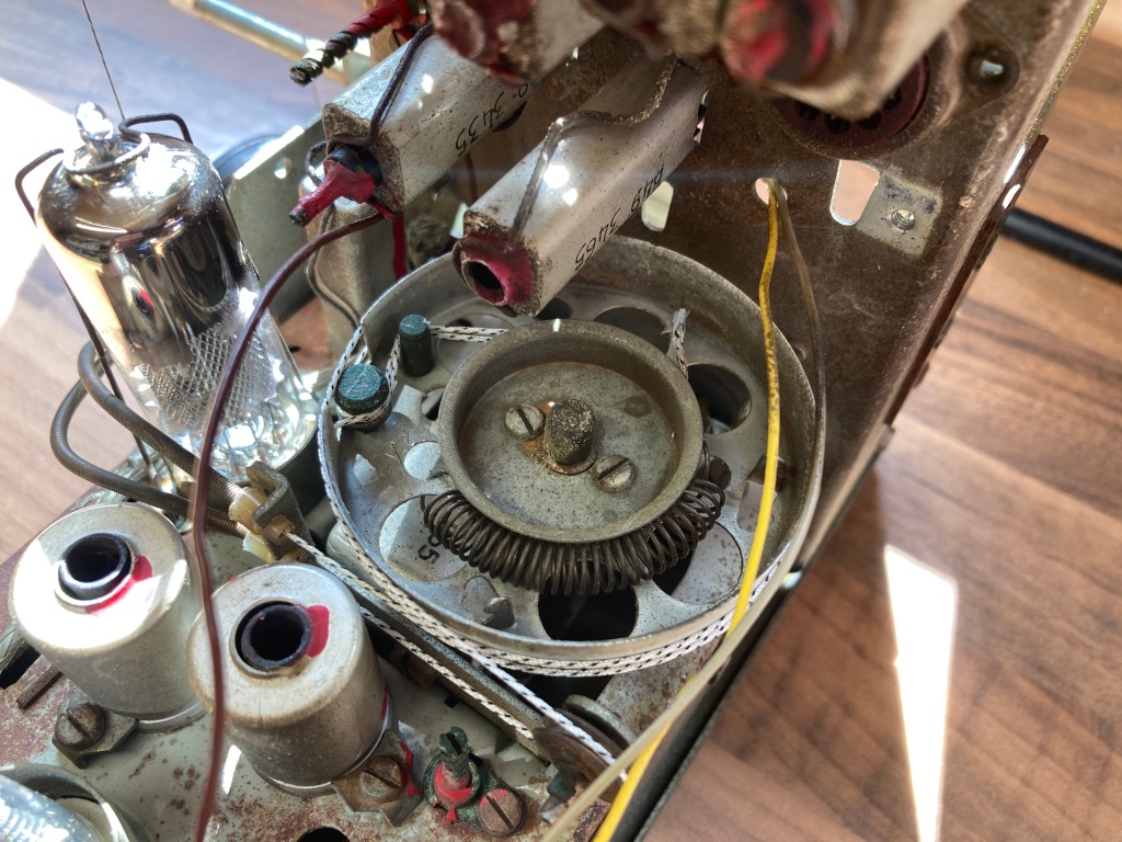 Tuning capacitor and the new cord.
I tested the tuning cord out, and it worked as expected – I had to increase the tension slightly by shortening the cord, as I found that the cord slipped on the tuning control when the dial cord was installed. After adjustment, it worked fine.
Front Fabric Replacement
The original front fabric was completely baked out – it was supposed to be a lovely gold colour with red stitching, but had both faded and deteriorated with age and use. I made attempts to clean it up, but this made little difference.
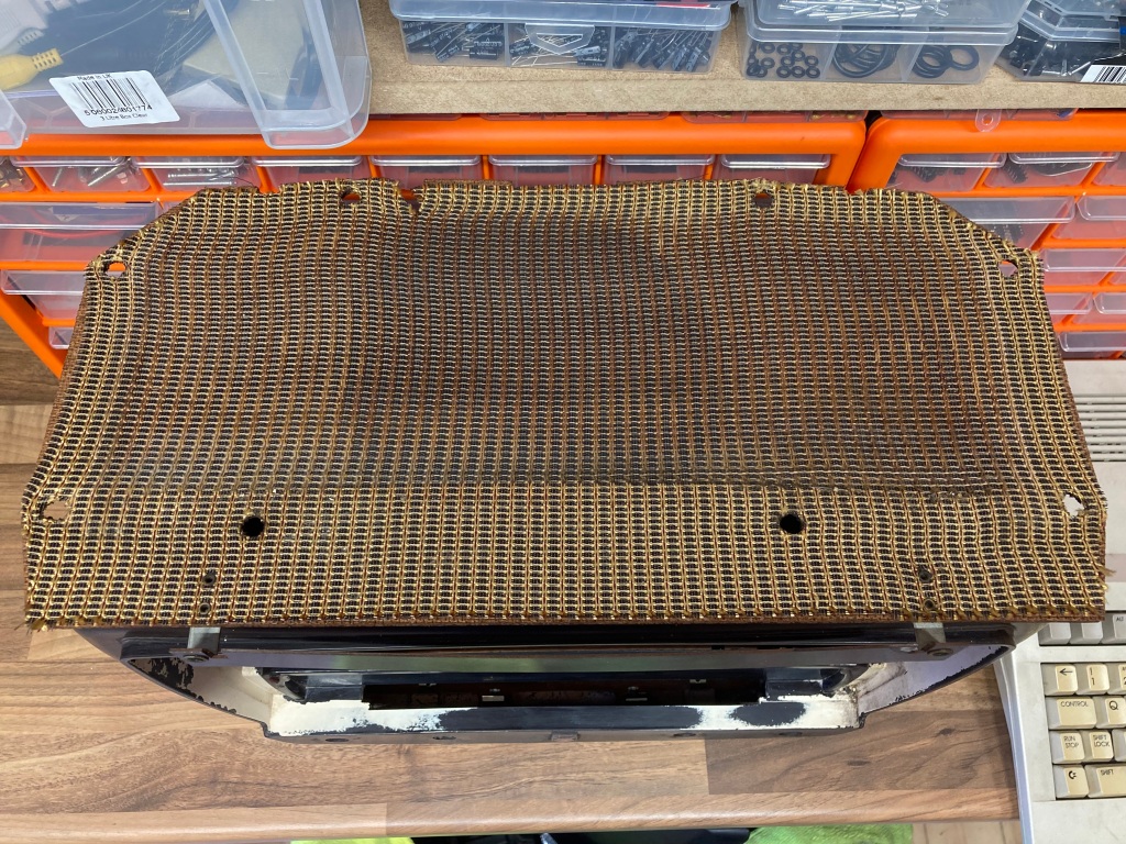
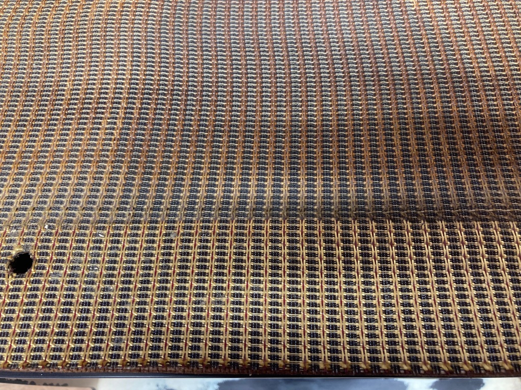
Original front fabric.
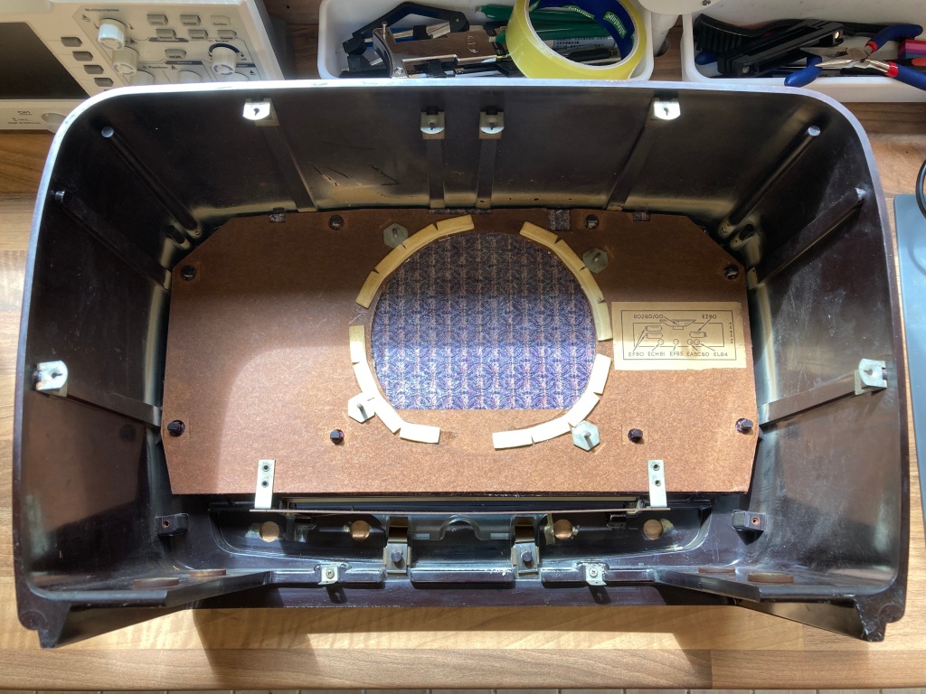
The original fabric was just held in place with crusty old contact adhesive, to it was pretty easy to remove, and it went straight in the bin.
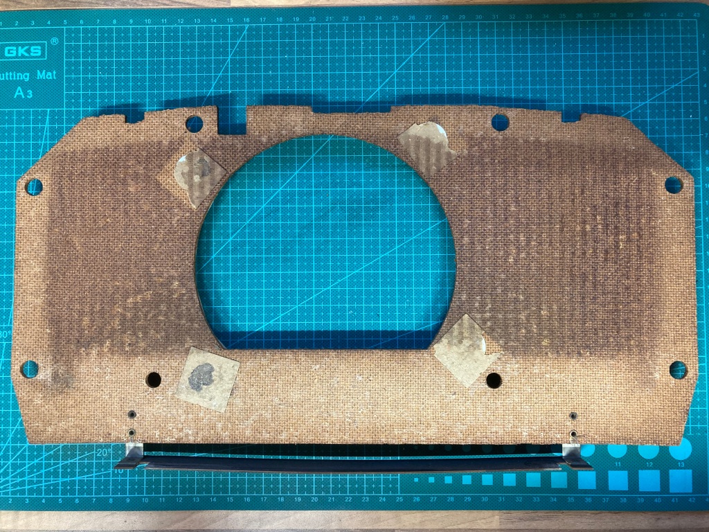
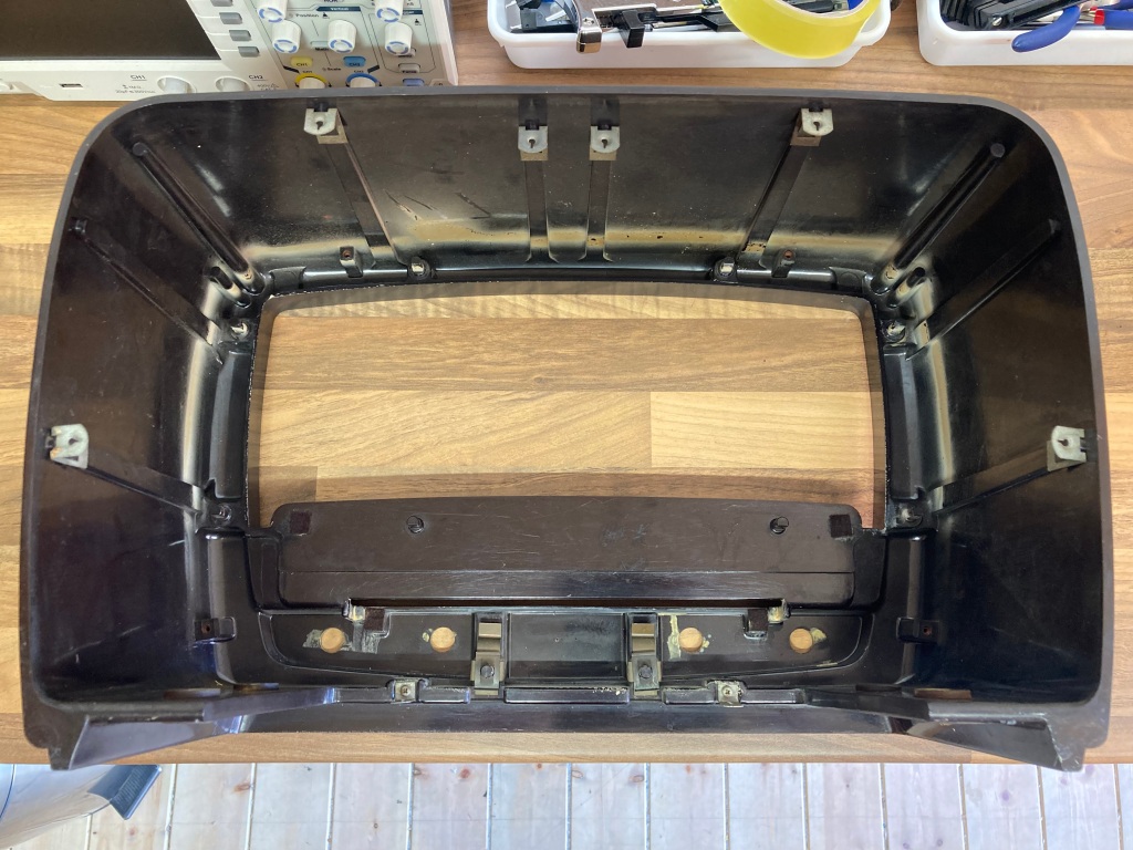
Fabric removed from the front cover.
I decided to replace it with a modern-made replacement fabric, designed for use with vintage radios – I bought an 18″ by 18″ cloth and cut it down roughly to size.
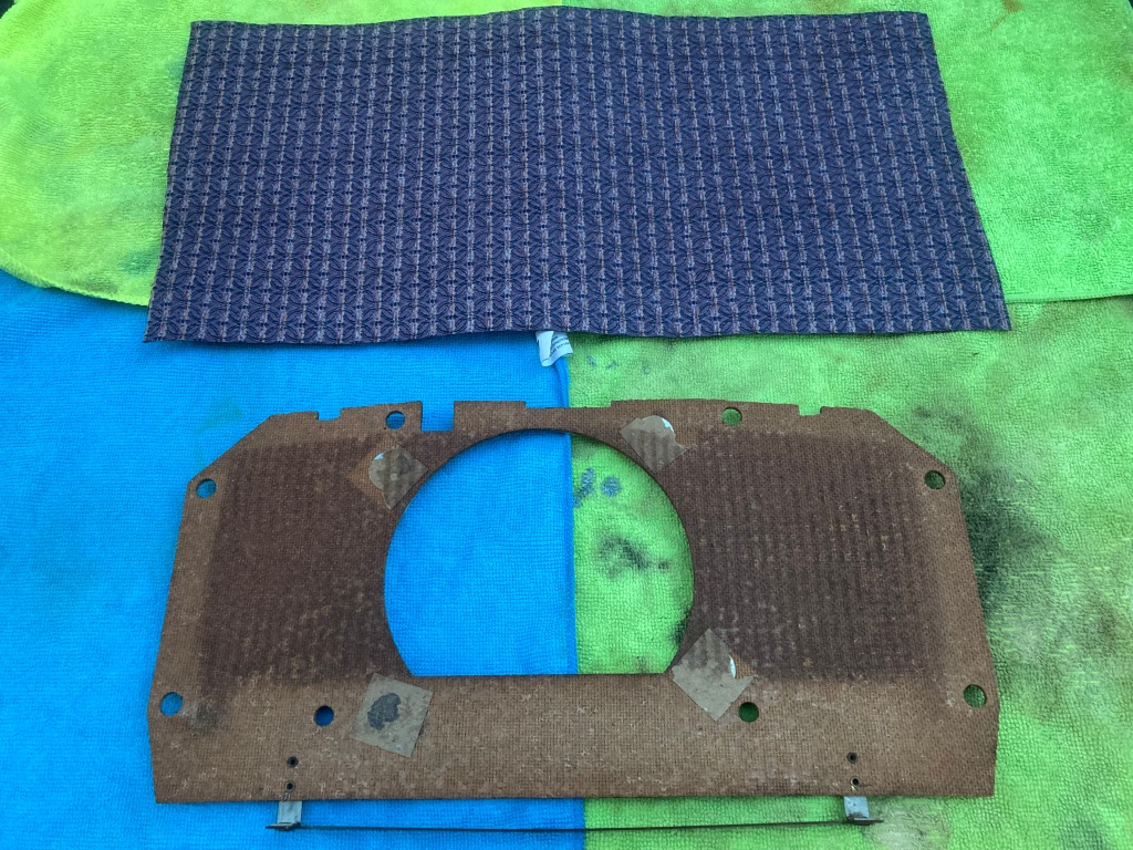
Cloth cut to size.
I used some heavy-duty contact adhesive to attach the new fabric, lightly spraying both mating surfaces, leaving the adhesive to go tacky, then applying the fabric.
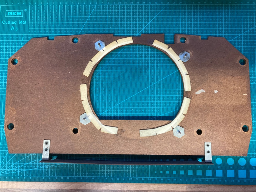
I then cut the fabric around the outline of the front panel, and used a craft knife to nick the fabric where all of the mounting holes are.
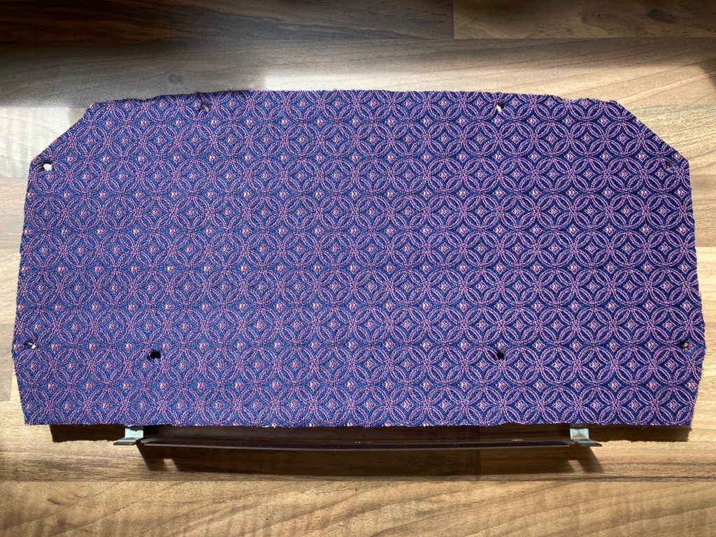
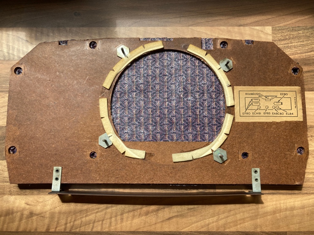
Front cover with replacement fabric fitted.
Case Cleaning & Polishing
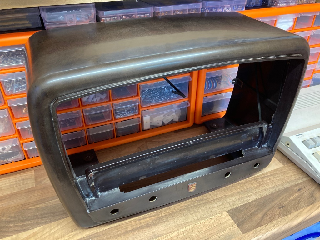
The bakelite case seemed in very good condition with no scratches or cracks, however it was absolutely filthy and dull with age, and the cream paint around the inside edge of the front bezel was badly flaked.
I started with a thorough clean with degreaser and a microfibre cloth, to get rid of the worst of the dirt. Then, I set about removing the bulk of the paint from the front bezel using acetone – bakelite is tough stuff, so this wasn’t a problem.
Then, I polished the case exterior thoroughly using Brasso wadding until it had a nice, deep shine – it’s important not to cut too deep into the bakelite, as you can expose the filler material (which sometimes contains asbestos).
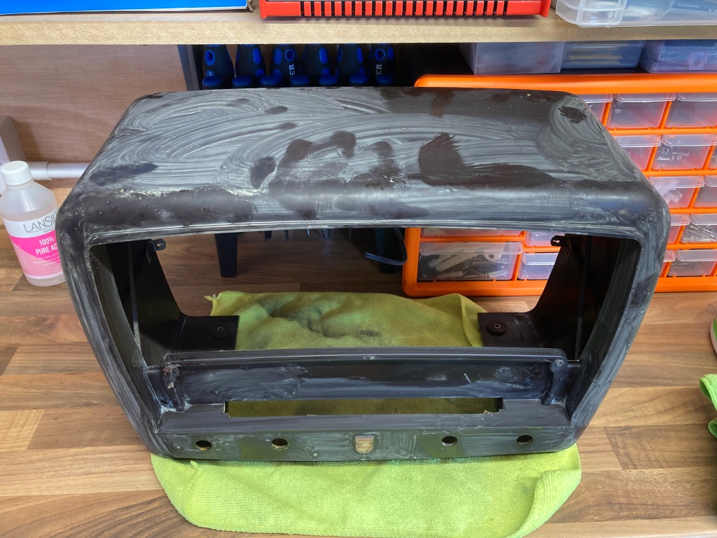
I then gave the case a final clean, and removed the last of the paint – the front looked really nice without it, so I didn’t try to repaint it.
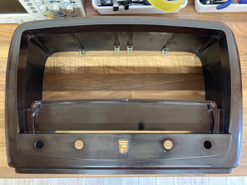
Radio case following polishing.
The front glass is simply held in-place with clips – it was very dirty and coated in flecks of paint, so I removed it for cleaning with degreaser and a microfibre cloth. The paint used on the dial glass on vintage radios is often very delicate, so should not be touched if possible.
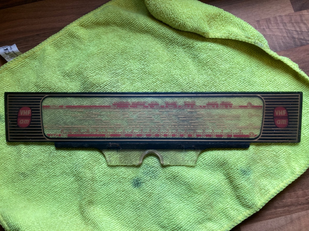
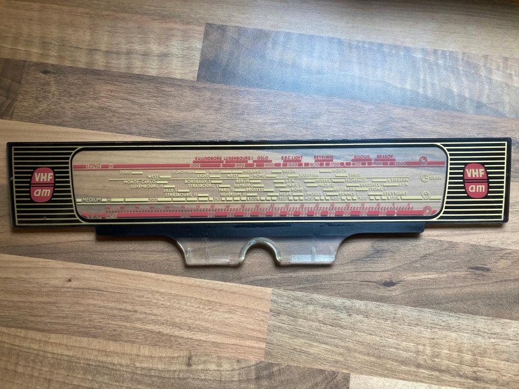
Front glass before and after cleaning.
The control knobs were also cleaned – the original gold leaf around the edge was covered in grime and corrosion, but came up quite well despite.
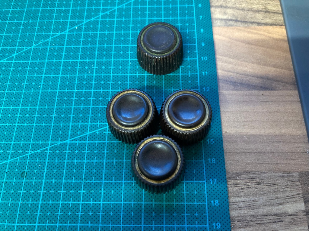
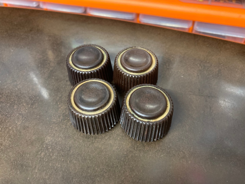
Control knobs cleaned.
Radio Reassembly
Reassembling the radio is just the opposite of its disassembly.
The first step is fitting the dial cord, the procedure for which is documented thoroughly in the 353A service manual. I replaced the original spring, which was worn out.
Dial cord fitting information (image credit: RadioMuseum.org).
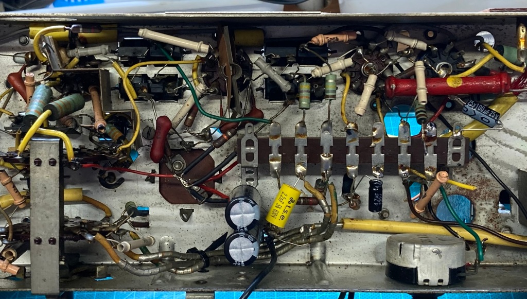
Radio chassis following restoration.
The front cover fits into the front of the radio case, and is held in place by eight push fittings – the speaker is held in place by four bolts and holding bars (I added removable connectors to the speaker to aid in reassembly and disassembly.
The chassis is then connected to the speaker, and screwed into place.
Radio chassis reinstalled.
The dial indicator can then be fitted – this is held in place on the dial cord by wrapping the cord around it a couple of times.
Dial indicator installed.
Then, the bottom and rear cover can be reinstalled.

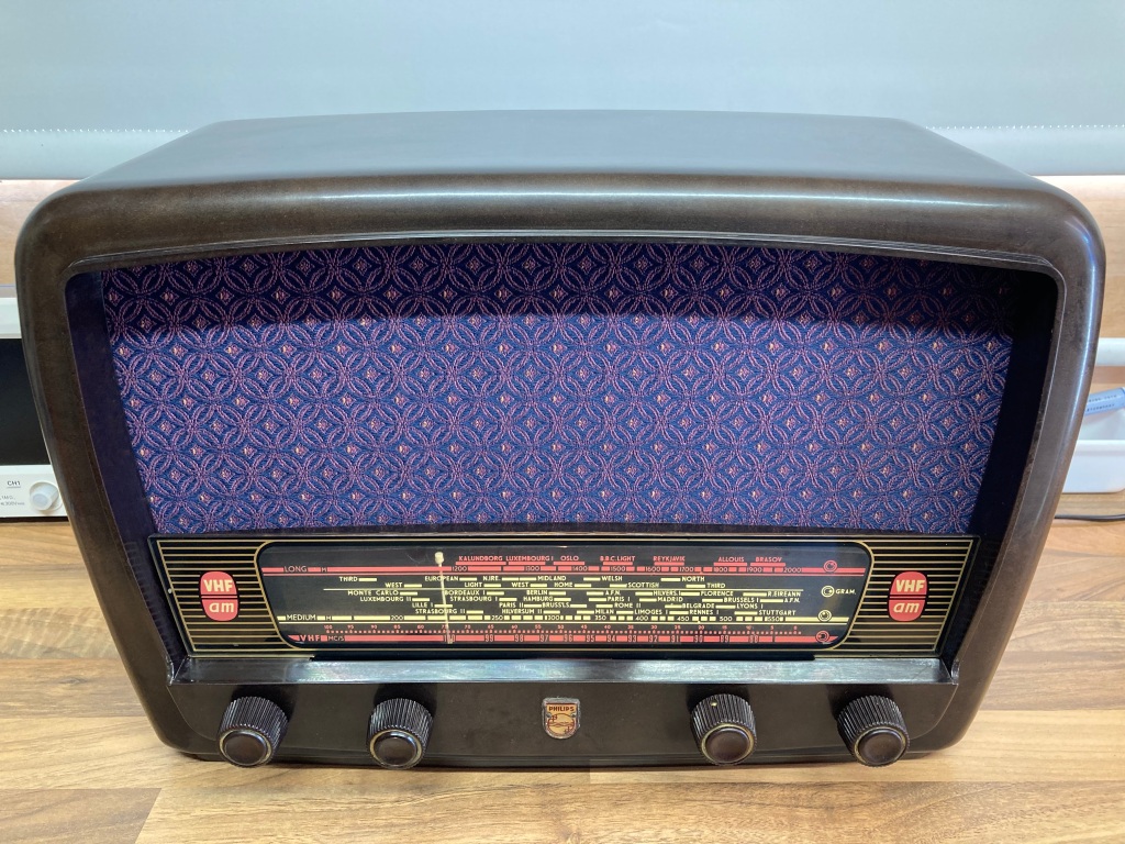
 Philips 353A radio following restoration.
Radio Testing
I originally tested the radio chassis outside of the case, just in case any other work needed to be done. For the first power-on, I used the dim-bulb tester that I made (which would limit the current drawn by the radio in case of a problem such as short-circuit, hopefully avoiding potential damage) connected to my 300W mains isolation transformer via a mains power meter for safety and consumption monitoring.
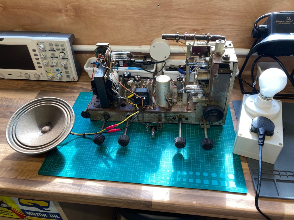
Initial testing using a dim-bulb tester.
When powered up from the limited supply, the dial lamp glowed dimly and the tube heaters seemed to light up okay – the 60W bulb on the dim-bulb tester didn’t light up noticeably and the power meter was showing about 30W, so there didn’t seem to be any immediate issues. I bypassed the bulb, and the radio seemed to work great.
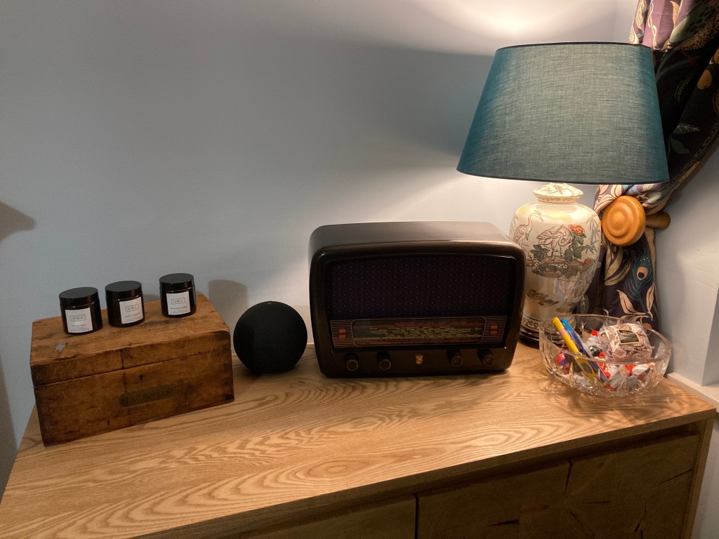
Philips 353A radio set up in our front room.
I also tested the radio again when it was fully reassembled, and checked all the controls – it sounds amazing, even better in the case!
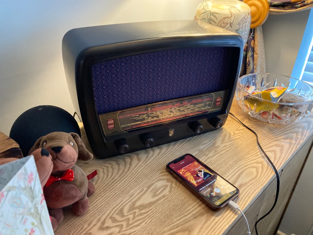
Philips 353A radio playing music from a modern smartphone.
I also made up an audio input adapter cable, which connects via the gramophone pickup and allows us to bypass the AM/FM demodulation section and use the radio as an audio amplifier – it sounds brilliant. This is safe to do (if done properly) as the 353A has a mains transformer and the chassis is not connected directly or indirectly to the mains input, however this is not the case on all vintage radios, so take care.
Overall, I’m extremely happy with the impressive outcome of this restoration.
Philips 353A radio before and after photos.
Recommend
About Joyk
Aggregate valuable and interesting links.
Joyk means Joy of geeK