

a c i d b o u r b o n
source link: https://acidbourbon.wordpress.com/2021/04/11/a-74xx-defined-radio/
Go to the source link to view the article. You can view the picture content, updated content and better typesetting reading experience. If the link is broken, please click the button below to view the snapshot at that time.
Video Appetizer
I built a shortwave radio receiver from scratch using only cheap and easily available components, i.e. standard transistors, op-amps and 74xx logic chips. No typical radio parts – no coils, no variable capacitors, no exotic diodes. This project is easy to build and gives you a hands-on experience with radio technology which you won’t get from a fully integrated SDR.
Here is the schematic.
Motivation
A friend of mine had an idea: He wanted to build a guitar FX pedal that is essentially a short wave radio receiver. It should use the guitar cable as an antenna and it should be very straightforward to build. No weird coils, no exotic rotary capacitors, no Russian voodoo detector diodes. And it would be okay (or even desirable) if it’d be LoFi. He had some weird sound experiments in mind, probably in combination with synthesizers and funny effects.
So he asked me if I had an opinion on how to build such a thing. I answered that I am not the “radio type” of tinkerer. I had never built anything resembling a ham radio and had never played with a software defined radio receiver. But I said that “at least I think I understand the general working principle of AM radio“.
So, long story short, my friend had me “nerd-sniped” and I found myself doing some LTspice simulations … modulating/multiplying sine waves, etc. Let’s sum up the rules (“dogmas”) again that I set for myself:
- No coils and no transformers -> No tuned LC circuits
- No (mechanically) variable capacitors -> No tuned LC circuits
- No special/exotic diodes
- Must receive short wave broadcasts
- KISS (Keep It Simple, Stupid)
So essentially to build a radio from scratch with no radio parts … but at the same time as simple as possible.
The Heterodyne – An old but smart concept
So I consulted the Wikipedia page about short wave broadcast and I learned that short wave is defined as everything ranging from 3 to 30 MHz. And I figured that, due to my self-proclaimed ban of LC-circuits, I probably want to build a heterodyne receiver.

(Picture embedded from Wikipedia)
I’m not going to explain the heterodyne receiver in full glory here, there are others who already have done a good job doing just that. Let’s just highlight the most important idea: A tunable oscillator (the “Local Oscillator”) is tuned to a frequency not identical but very close to the carrier frequency of the radio station that we want to tune in to. The received carrier and the local oscillator waveforms are fed into an “RF Mixer”, a device that essentially performs an analog multiplication. The two slightly out of tune waves will “beat against each other” in the mix, with the beat frequency being exactly the frequency difference of the input signals.

For example: We have a radio station broadcasting at 10 MHz and we tune our local oscillator to 10.1 MHz, then the signal after the mixer will have a signal component oscillating at 10.1 MHz – 10 MHz = 100 kHz. The catch: The 100 kHz signal still has the same envelope function as the the 10 MHz AM station, i.e. the same audio information that was modulated onto the carrier. We basically only “tune down” the carrier wave, without changing the information that is carried. The beat frequency is often called IF – intermediate frequency.


Why do we do that? Because the lower the frequency of the signals, the easier it becomes to amplify and filter them! So in order to listen to our station we have to have a bandpass filter and filter out and amplify only the intermediate signal at (in our example) 100 kHz. Be aware that all the other stations have also been mixed with the local oscillator and have landed at some other intermediate frequency (that we don’t want to listen to). Because we already have a tunable local oscillator that determines which station lands where after the mixing, the IF band pass filter can be set to a fixed frequency (here 100 kHz).
Now all we have to do is rectify and low-pass filter the selected IF signal to recover the envelope function (i.e. the AM audio information).

The most humble mixer
Okay, so the heart of a heterodyne receiver is a RF mixer. I did some googling and found the classical implementations:
- There is the famous diode ring mixer, which is technically identical to the famous ring modulator sound effect you might know from pop music. It relies on signal transformers to generate galvanically insulated input and output signals. It did not fit my design dogmas.
- There is the Gilbert Cell mixer, a clever discrete analog circuit comprising six transistors to implement an analog multiplier. The Gilbert Cell, too, has differential signal inputs and outputs. Although six transistors look like an okay amount of complexity, the prospect of biasing all of them properly turned me off a bit. There is a very nice integrated Gilbert Cell IC, the NE612/SA612, which is sort of straightforward to use, but it is not really a convenient off-the-shelf component, that you find in every hobbyist distributor’s online shop. Also it is rather priceous (around 2€) and I was only able to get an SMD package.
I was reading some more about RF mixer theory and I came across this document from analog devices which seems to be a course about RF/IF circuits. In the theoretical introduction to RF mixers they discussed an ideal (switching) RF mixer:

An ideal switching mixer
I have never viewed it like this before, but it sort of makes sense: Make two copies of the RF input signal with opposite polarities and switch between these two at a fixed frequency f_LO. This is effectively the same as multiplying (mixing) the RF input signal with a square wave of frequency f_LO. Well, mixing with a square wave is not exactly the same as mixing with a pure sine wave (because you also mix with the higher order harmonics of the local oscillator frequency) but for building our heterodyne short wave receiver it does not make that big of a difference.

In the analog devices course they went on and discussed the diode ring and the Gilbert Cell mixer as examples of real-world mixers, which gave me the impression that using an actual switch as a mixer is impractical or yields poor results. Also the usual sources of RF circuit knowledge on the web don’t seem to mention switching mixers that often.
But I wanted to see it with my own eyes. At least I wanted to build a crappy mixer to see that the principle works. Yes, using an actual mechanical switch is very much impractical, if we are talking about reversing the polarity of an RF signal several million times a second. But what about a good old analog multiplexer? For example the humble 74HC4051?
The 74HC4051 has 8 analog inputs, A0-A7, and one analog output A (or 1 in and 8 out, the switch works both ways). Internally the ‘HC4051 acts just like a single-pole 8 throw switch. The switch position is determined by the three logical select inputs S0, S1 and S2.
So in order to use it as a mixer, we first use our good old friend, the 2N3904 npn transistor, wired as a phase splitter (like an emitter follower, but you get an additional inverted copy for free). This will give us a positive and a negative (inverted) copy of the RF input. This is fed to the analog inputs A0 and A1 of the multiplexer. The local oscillator waveform has to be provided as a logical TTL or CMOS signal and is fed into S0. S1 and S2 are wired to GND, this way we will only switch between A0 and A1. The IF output (A) is then connected to the base of another 2N3904 wired as an emitter follower, just to buffer the signal in order to drive the next stage.

I tested it with a two channel signal generator and an oscilloscope. The above device behaves exactly like an ideal switching mixer! In the below example I mixed a 30 MHz sine wave at the RF input with a 31 MHz square wave at the LO input. The result is this spiky beast of a waveform. But unmistakably the dominating low frequency component is a sine wave at 1 MHz. Hooray! It might not be the best mixer ever. But it was cheap and straightforward and seems to work up to 50 MHz until you begin to see noticeable injection loss. Over the entire short wave band (3-30 MHz) the mixer works with a gain of more or less exactly 1. I am impressed.
A caveat: Please use the 74HC4051 chip and not its older and slower cousin the MOS4051.

A simple RF local oscillator
Okay, we have our mixer. Now we need a local oscillator that provides a stable rhythm by which to flick the switch. Desired frequency range: The entire shortwave band of 3-30 MHz. Luckily the toolbox of 74xx chips provides exactly what we are looking for! It is called 74HC4046 and it is a Phase Locked Loop (PLL) IC. A PLL always comprises a voltage controlled oscillator (VCO) in combination with a phase detector which compares the phase of the VCO with the phase of the oscillation that the PLL is supposed to synchronize with. But let’s not talk about PLLs. We are only interested in the first half of the chip – the VCO.
Elliot Williams from Hackaday.com has written a very nice article introducing the ‘4046 as a fun an versatile source of logic noise synthesizer sounds: https://hackaday.com/2015/08/07/logic-noise-4046-voltage-controlled-oscillator-part-one/
This basically explains everything about the ‘4046 you need to know. We’ll be using it in a similar way, but not in the audio frequency range, but at much higher frequencies. This is achieved by changing the external resistor and capacitor to smaller values. By trial and error I ended up with 10k and 47p. Tuning the oscillator (and thus selecting the radio station) is done via two regular potentiometers. One for coarse and one for fine tuning. Making the second poti a fine tuner is achieved simply by connecting it though a ten times larger resistor than the coarse tuner. This way its influence on the VCO control voltage is also ten times smaller.

A caveat: Please do use an actual 74HC(T)4046 and not it’s older and slower cousin the MOS4046 (aka HEF4046, CD4046). I got good results with a Texas Instruments CD74HCT4046 (with a T). Funny enough I got bad results (too slow, too low frequency) with a Texas Instruments CD74HC4046 (without the T), even though the datasheets claimed both chips have similar performance. If possible, check the frequency range of the oscillator output with an oscilloscope or with a frequency counter. You don’t actually have to have an oscilloscope that can measure all the way up to 30 MHz. You could feed the output of the VCO into the clock input (CP) of a 74HC4024 (7-stage binary counter) and study the output of its Q6 output. It gives you a square wave with 1/128 the frequency of the VCO (30 MHz/128 = 234.375 kHz). This is something you can study with a very cheap oscilloscope. Or you could just count oscillation cycles with an Arduino. If this is still too fast for your measurement device, then just cascade two 74HC4024 and divide the frequency by some more factors of two.
IF filter and amplifier
Mixer – check, local oscillator – check, now we need a narrow filter! Remember, we want to pick out one narrow frequency band which we want amplified, all other mixing products which don’t land near our target frequency (here 100 kHz) shall be suppressed. Once again: no tuned LC circuits! So we go for a classic op amp band pass:

An LTspice simulation helps us selecting the right values to get our filter response right. In the end we want a very high gain and a small resonance maximum. But not infinitely small: The bandwidth of the pass band should be at least around 5 kHz, otherwise you don’t have enough bandwidth to fit in a significant part of the audio spectrum.
Note that the virtual GND of the OpAmp is at half the VCC = 2.5V. This reference voltage is created with a resistive divider and stabilized by a 100n capacitor. The 2.5V reference is also used for the demodulator OpAmp.

Maybe this is not the most ideal IF filter, but it does the job 
Demodulator
Okay. After the IF filter we have a single 100 kHz sine wave with audio information modulated onto it. To get to the audio we “only” have to rectify the waveform and smoothen it a bit with a low-pass filter.
A lot of classical AM demodulator circuits that I found on the web use a germanium or Schottky diode as a half-wave rectifier (to cut away the negative half of the IF wave). They perform better than your regular silicon diodes, because they have a lower threshold voltage and thus can rectify smaller input signals. But what if we don’t have and don’t want to buy special magic radio diodes?

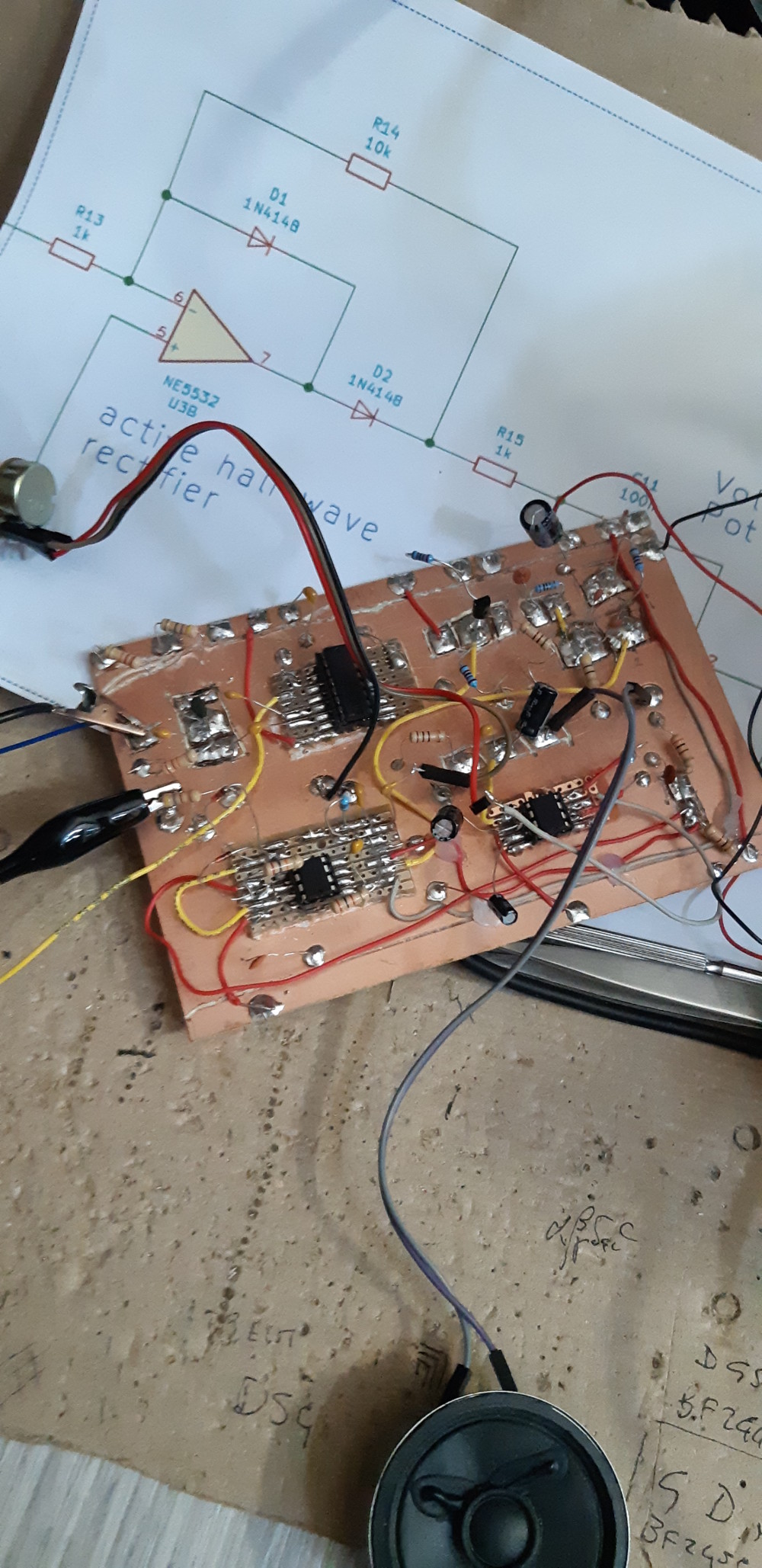
Fear not, there is a nice OpAmp circuit that goes by the name of “active half wave rectifier” and makes the use of special diodes obsolete. Here we use negative feedback to actively mitigate the finite threshold of the rectifier diode (D2). The second diode (D1) is only there to limit the negative output swing during the negative (removed) half wave. By choosing the feedback resistor ten times larger than the input resistor (R14/R13=10) we also get a gain factor of 10 for free.
R15 and C10 form a low-pass filter that reduces the depth of the high frequency ripples (stuff that you don’t hear anyway). In the end we have a volume poti and an AUX-level audio output jack.
Wrap-Up
Here is the complete schematic.
As you see and hear it works … and it makes some nice cliché AM radio noises. As an antenna I used a thin wire, circa 6 meters long, fixed with thumbtacks to the wall.
If your reception is poor – do not despair. Sometimes the air is full of radio stations some hours later. Shortwave reception depends massively on the time of day (because sun and atmosphere and stuff).
You can cross check your results with an interactive WebSDR, like this well-crafted Web-App for a receiver in the Netherlands: http://websdr.ewi.utwente.nl:8901/ … there are others, maybe you find one near your area.
(Picture embedded from Wikipedia)
One more thing: In the initial heterodyne block diagram (which I borrowed from Wikipedia) you see an RF filter and and RF amplifier. If you payed close attention you’ll have noticed that I have built no such things.
I noticed that the receiver worked just fine when I attach the antenna directly to the mixer. The necessary signal gain comes solely from the active IF filter (in theory x100) and the active rectifier (x10). If we amplify only the frequency that we already tuned in to, then we don’t need an RF filter anyways. This way we can keep it nice and simple. After all this is just for fun.
Hope you succeed in building your own receiver. Please do send me a video of your receiver in action!
Bonus section
If you read this far, then you already have your basic receiver. But you can make it slightly better
In the following video you see the shortwave receiver with both “upgrades”, the Arduino controlled local oscillator and an additional RF filter+amplifier. The mini oscilloscope displays the amplified and filtered IF waveform before the demodulator.
Optional Upgrade I: A better local oscillator
The most wacky part of the whole system is the local oscillator. If you want precision tuning and excellent stability you can buy a ready made HF clock generator. There is an inexpensive and very versatile Arduino breakout board out there that’s based on the si5351 chip.

Here is a link to the original module from Adafruit: https://learn.adafruit.com/adafruit-si5351-clock-generator-breakout
It can synthesize you anything between 8 kHz and 160 MHz with quartz perfection. It has an i2c interface and can be programmed with any arduino. There exists a control library that works straight out of the box: https://github.com/adafruit/Adafruit_Si5351_Library – or just search for “si5351” in your Arduino library manager. Just connect one of the clock outputs to the S0 input of the 74HC4051-mixer and you’re good to go.
There exist China copies of this board that you can get for less than 5€ including shipping – and they work with the Adafruit library just as fine.
Optional Upgrade II: RF input amplifier
I just told you that the radio works perfectly fine without the RF filter and amplifier before the mixer. And it does.
But: Maybe you understand more about antennas than me and, say, you have built a very compact antenna that has very cool properties but picks up less RF than my 6 m wire. So you wish you can get a little more RF signal gain from the electronics.
Okay, so here is a simple RF filter and amplifier to have some more flexibility regarding input gain. The first block is a (quick and dirty) second-order high-pass filter that just suppresses everything below roughly 1 MHz. I expect the antenna to pick up first of all 50 Hz power line hum and switching power supply interference in the dozens to hundreds of kilohertz range. Feeding this dirt into the RF amplifier might lead to clipping and distortion of the amplified waveform (destroying information). We don’t want that, so we filter it out before the amplifier.
The second block – The RF amplifier, makes use of a cheap HF transistor – the BFR92 – to boost our RF signal by a factor of 50. I could only find it in an SMD package. But fear not, with a bit of fiddling you can solder it on a regular protoboard. The output of the RF amp can be connected to the antenna input of the RF mixer module.
A logarithmic potentiometer between filter and amplifier lets you adjust the gain of the RF input circuit.

Here is the schematic as PDF.
Visitor Showcase
As I mentioned in the introduction, the whole project started with the FX pedal idea of my friend [Sten]. Meanwhile he also tried and succeeded at building his shortwave FX pedal. Here is a demo of the beauty. Since it’s designed to generate radio NOISE and is fed into a guitar amplifier … expect the sound to be noisy. In this case it is a FEATURE!  Remember the antenna IS the guitar cable (and the guitar).
Video by StenVideo by Sten
Here is another build from our friend Vito from Italy – This looks like a REAL radio build!
If you have build a 74xx shortwave receiver, too, please do send me a picture or youtube link. I’d be glad to showcase it here.
Recommend
About Joyk
Aggregate valuable and interesting links.
Joyk means Joy of geeK