

Creating Reusable Characters With Blender and Unity [FREE]
source link: https://www.raywenderlich.com/31539225-creating-reusable-characters-with-blender-and-unity
Go to the source link to view the article. You can view the picture content, updated content and better typesetting reading experience. If the link is broken, please click the button below to view the snapshot at that time.
Creating Reusable Characters With Blender and Unity
Characters in video games are often as memorable as the accompanying gameplay and music. In this tutorial, you’ll learn how to prepare a humanoid model using Blender and how to bring it into Unity.
Version
Artists create 3D characters for your favorite games with the use of models, textures and animations.
In the past, characters needed to have the exact same skeleton to share animations. This limited character diversity as their height and proportions had to be the same as well. As an amusing example, the older FIFA games had players all be the same size because creating a separate skeleton — and a set of animations — would have been a nightmare.
Nowadays, most game engines come with a system to allow reusing animations as long as the skeletal hierarchy is compatible. This allows you to use the same animations for characters of all shapes and sizes. In Unity, this system is called Mecanim. It allows for easy set up of animations, the blending between them and retargeting of humanoid animations between models.
Being able to reuse animations allows you to use animations from the asset store and websites like mixamo.com for your own custom characters. This saves a ton of time!
In this tutorial, you’ll learn how to prepare a humanoid model using Blender and how to bring it into Unity. More specifically, you’ll learn how to:
- Create an armature (skeleton) for a character and rig it
- Enhance the character with accessories and objects
- Export a model to FBX
- Import Blender models into Unity
- Create and tweak a humanoid avatar
- Attach objects to a character
- Animate a humanoid in Unity
Time to jump right in!
Getting Started
Before you begin, verify you meet the following requirements:
- You’ve downloaded and installed the latest 2020.3 LTS release of Unity.
- The latest stable 64-bit version of Blender is installed on your machine.
- You have a minimal understanding of the Unity editor. Check out some of the beginner tutorials on the website.
- Some experience with Blender is recommended. Here is a good tutorial to get started.
Download the source materials by clicking the link at the top or bottom of this tutorial and unzip it somewhere.
Open the Starter folder and navigate to the Assets\RW\Models folder. Now open CuteCharacter.blend in Blender.
The file contains the following:
- A low poly humanoid character model
- The CuteCharacter material
- A reference to the CuteBase texture contained in the same folder as the model
After opening the file, you should see the character model on the left:

Note that it’s mirrored on the X-axis, meaning its left and right side are identical. This will make the whole process a lot easier along the way.
The right side of Blender has a simple texture image loaded:

Time to get to work! The first step to animating this character is rigging it.
Rigging the Character
Rigging is the art of creating an armature, the skeleton of the model. An armature has bones to which you can connect vertices, so they move along whenever a bone gets moved around.

Hover over the 3D View to bring it into focus. Now add a new armature by holding Shift and pressing A to open the Add Menu. Next, select Armature to add the first bone.

You’ve now created the armature and its first bone, also known as the “root bone”. With the armature still selected, find the In Front check box in the Viewport Display section of the Object Properties tab and check it.

The armature is now visible through the character making the skeleton creation process a lot easier.

Before diving in and creating the full skeletal structure, it’s important to understand how it needs to be set up to be compatible with Unity’s Humanoid Avatar.
Due to the way Unity maps the bones to its own system, some key bones are necessary.
![]()
Unity expects at least 15 bones, which are:
- Hips (root bone)
- Lower spine
- Upper spine
- Two upper arms
- Two lower arms
- Two hands
- Two upper legs
- Two lower legs
The rig you’ll be creating includes all of the above bones and some extra ones for added stability when animating.
Make sure the armature is still selected and press Tab to enter Edit mode. Next, select the root bone by clicking it.

Now open the Bone Properties tab on the right in the Properties editor and rename the root bone to Hips by entering it in the name field and pressing Enter.

Spine
With the first bone made, you can now transform it into a spine for the character.
Select the bottom, sphere shaped connector of the Hips bone. Next, press G, Z, 0.5 and Enter in sequence to move it up around where you’d expect the center of the hips to be.

Now, select the top connector and press G, Z, 0.1 and Enter to move it up a bit.

To get more spine bones, you’ll need to subdivide the Hips bone in three pieces. Select the Hips bone, right-click to open the context menu and select Subdivide. By default, this makes a single cut, splitting the bone into two pieces. To increase the number of cuts, open the Subdivide menu at the bottom left of the 3D view and set Number of Cuts to 2.

With the spine split, the new bones are named Hips.001 and Hips.002. That’s not a good way of naming bones; rename the bones by selecting each one and changing the name in the Bone Properties tab of the Properties editor on the right like you did with the Hips bone.
Name the top one Chest and the middle one LowerSpine.

Next up are the leg bones. Duplicate the Hips bone by selecting it and then pressing Shift + D. Next, move it a tad to the right and right-click at the end to reset the position of the new bone.

If you look at the Bone Properties tab on the right, you’ll see a bone named Hips.001 selected.
Rename this bone to UpperLeg.L. The L stands for left, this makes it clear what side the bone is on and will help with mirroring later on.
This bone needs to point down and be placed right above the knee. To start off, rotate the UpperLeg.L bone 180 degrees on the Y axis by pressing R, Y, 180 and Enter in succession.

Now move it in place horizontally by pressing G, X, .23 and Enter in that order. After that, press G, Z, -.2 and Enter to get it in position vertically.

Select the bottom connector and move it down by pressing G, Z, -.3 and Enter in that order.

You now have one large bone for a leg. If this character had wooden peg legs, this would’ve been perfect already! Most people have knees so they can bend their legs though, so you’ll need to make it bendable.
To do that, select the UpperLeg.L bone, right-click and select Subdivide to split the leg in two (ouch!). This results in two leg bones with a connector in the middle that will act a knee. Go ahead and the new bottom bone LowerLeg.L.

The last part of the legs are the feet. Switch to a side view by pressing 3 on your numpad and press period (.) on your numpad to focus on the lower leg.


Now select the bottom connector and extend it to make a foot bone by pressing E, Y, -.18 and Enter.

Next, rename the newly created bone to Foot.L using the Bone Properties tab.
Now might be a good time to save the file. Press CTRL + S and you’ll notice a small notice appearing at the bottom of the window. Feel free to do this periodically, better safe than sorry!

Switch back to the front view by pressing 1 on your numpad. Before moving on to the head, you’ll need to parent the leg to the hips. Luckily this is pretty simple!
Select UpperLeg.L and expand the Relations section of the Bone Properties tab. Click on the Parent drop-down and select Hips.

Torso
On to the head! Select the connector at the top of the Chest bone, press E, Z, .055 and Enter consecutively. This is the neck bone so name it Neck in the Bone Properties tab.

To add the head bone, keep the top connector selected and press E, Z, .95 and Enter in that order.

Name the newly created bone Head.
Next is the left shoulder connector. Select the top connector of the Chest bone and press E, X, .08 and Enter to add the new bone. Move it down a bit by selecting the rightmost connector and pressing G, Z, -.09 and Enter.

Name this bone ShoulderConnector.L. This bone will connect the chest to the shoulder. None of this is anatomically correct in any way, and it doesn’t need to be. :]
Next up is the arm itself! Select the rightmost connector of ShoulderConnector.L and press E, X, .85 and Enter in that order. This creates one large bone that needs to be split up to create the remaining bones for the left side.

Select the newly made arm bone, right-click and choose Subdivide in the context menu. Change the number of cuts in the bottom left to 3, so you get four pieces in total.

Name these bones as follows, from left to right:
- Shoulder.L
- UpperArm.L
- LowerArm.L
- Hand.L

The way these bones are laid out might look good at first glance, but because the way the connector between the arm pieces sits (also known as an elbow), the arm won’t be able to bend correctly. Hold Z to open the shading menu and drag your cursor to the left to enter the wireframe view.

Now take a look at the bend in the arm:

The red line indicates where the elbow is now and the white line indicates the arm’s bending point on the mesh. To fix this, select LowerArm.L and move it to the right by typing G, X, .09 and Enter.

Now switch back to Solid rendering by holding Z and moving your cursor to the right.
That’s it as far as adding bones goes. How about the right side though? Well, I don’t know about you, but I’ll take any shortcut I can get to get the work done! That’s why the next step is mirroring the bones on the left to the right with a few keystrokes.
Mirroring
Blender has a nifty feature to quickly mirror the bones of an armature in just a few simple steps! To start off, deselect all bones by holding Alt/Option and pressing A. Next, select the bones on the character’s left side (the right side when seen from the front) by holding Shift and clicking the bones one-by-one. Don’t forget about the foot!

With those bones selected, right-click and select Symmetrize in the context menu. This is all you need to do to get a perfect mirrored version of the selected bones:

The bones will also all have .R automatically at the end of their name instead of .L to signify what side of the body they’re used for.
Now save the file and prepare to move on to rigging.
Weight Painting
Weight painting is the process of binding bones to a 3D mesh. Each bone gets attached to a group of vertices with a certain amount of weight.
The weight decides how “hard” the vertices will be pulled and pushed by the bone.

Doing this manually would take a while since you’d have to paint the weight of every single bone. Luckily, Blender can take care of most of the grunt work by automatically weight painting based on how close the bones are to the vertices. This works by parenting the model to its armature and letting Blender automatically assign weights.
Press Tab to switch to Object mode. Click on the character model to select it, then hold Shift and click the armature to select that as well. The order you do this in is important, as the last selected object will be the parent. Now press CTRL + P to open the Parent menu and choose With Automatic Weights to parent the model to the armature and perform automatic weight painting.
On to the cool part! Select the armature, then change to Pose mode with the drop-down at the top left. Now select a bone and rotate it around by pressing R and moving your cursor around. Do this with each bone on the center and the model’s left side to check if everything the bones were weighted correctly.

After checking all of the bones, you may have noticed the eyes don’t move with the head, which looks a bit weird, to say the least!
To attach the eyes to the head, you’ll need to do some actual weight painting. Keep the armature in Pose mode, then hold Shift and click the model to add it to the selection. Now enter Weight Paint mode and prepare to do some painting.

This mode shows both the bones and the weight attached to them on parts of the model.
Start off by deselecting all bones by pressing ALT/Option + A. Next, hold Shift and click on the Head bone to select it. The weight colors go from dark blue, to green and finally red. As you can see, the eyes are dark blue, which means they aren’t attached to the head bone at all! To attach those eyes to the head bone you’ll need to increase their weight.
For easier access to the eyes and to strengthen the effect of adding weight, rotate the head bone backward by pressing R, X, -90 and Enter in that order. It looks grizzly, but don’t worry, he won’t feel a thing!

To attach the eyes to the Head bone, it needs some weight added to it. To start off, select the Add brush in the Brush section of the tool panel at the top left. By default, this is set to Subtract.

Now paint on the eyes to increase the weight until the eyes aren’t floating anymore.

To check out the result, reset the view by pressing numpad 1 and press Alt (or Option) + R to reset the rotation of the Head bone. The eyes are now correctly connected to the head.

With the basic weight painting done, it’s time to add some details.
Adding Accessories
Accessories in this context are objects that are attached to the character but aren’t a part of its body. This section discusses two ways of attaching objects: to the model itself and as a separate, reusable object that connects to a bone.
The former is a simple hat, and the latter is a weapon for the character to hold.

Before continuing, press A two times followed by Alt (or Option) + R to reset the rotation of all bones.
Editing the Character
The first way of adding more details to your character is easier to work with, but it comes with some limitations. As you’ll be working on the model itself — which is mirrored — all geometry added will be copied from the left side to the right and vice-versa. This makes it impossible to add anything unique to one side. Because the geometry is a part of a particular model, it also can’t be reused for other characters. It’s perfect for any situation where those limitations aren’t a problem.
If you’ve followed along with the tutorial until now, you’ll probably still be in Weight Paint mode. Press Tab to enter Edit mode and start off by switching the selection mode to Vertex by pressing 1 on your number row or by clicking the first button right of the mode dropdown.

Now select any vertex above the red line (which is an UV seam used for texturing) on top of the head by clicking on it. Next, press CTRL + L to select all connected vertices, this selects the whole model. Now select the UV delimiter by selecting UVs in the bottom left panel. The top of the head will be selected now.

Select the edge loop underneath as well by holding Shift and Alt (or Option) and then clicking on any of the first horizontal edges below.

Now duplicate the selected faces by pressing Shift + D and then clicking. Move the duplicated faces up a bit by pressing G, Z and 0.01 followed by Enter to confirm.

Next, scale the whole selection up by pressing S, 1.05 and Enter. This moves the hat away from the head a bit, so you don’t end up with some of the faces Z-fighting.
The hat is still floating around, so do the following to attach it to the model:
- Select just the bottom row of the “hat” by pressing ALT/Option + A to deselect everything. Now select the bottom edge row of the hat by holding Alt (or Option) and clicking on one of the bottom edges.
- Make it straight by press S, Z and 0 in that order.
- Press E to extrude and press Enter to confirm.
- Press S to start scaling and move your cursor towards the model until the edges are inside of the head. Rotate the view around to make this easier to see. Click to confirm the scaling.

This gave the hat some depth so it can look all right from all sides without any holes. A hat made from human skin probably isn’t what you had in mind though! To change the color, you’ll have to unwrap its UVs first so it can fit nicely on the texture.
Select the entire hat by selecting any vertex on the hat and then pressing CTRL + L. Change the delimiter to Normal this time to select all the connected vertices. For this hat, you’ll perform one of the easiest unwraps in existence: from the current view. Press numpad 1 to get a front view, then press U to open the Unwrap menu and select Project From View.

If you look at the right side of the Blender window where the texture is visible, you’ll notice some vertices were added that look similar to half of the hat:

You can select all of these by moving your cursor over to the texture and pressing A. Actions in Blender are context sensitive depending on where your cursor is placed, so make sure to keep it somewhere inside the region of the texture for now.
Now press G to move the UVs over to the blue splotch, confirm the movement by clicking and then scale the selection down until it fits inside the blue region by pressing S and confirming by clicking again.

If you now look at the character again, you’ll notice his hat turned blue!

Now, position the cursor back somewhere near the model on the left and press Tab to return to Weight Paint mode. Rotate the Head bone around a bit to check if the hat is connected.

It looks like you’re in luck! Because the vertices of the hat are all so near to the Head bone, they’re included automatically. If this wouldn’t be the case, you’d have to paint the hat like you did with the eyes.
Next up is creating and attaching a separate object.
Attaching Objects
For this part, you’ll be creating a simple staff that will act as a weapon for the character to hold. It’s easy to imagine a sword, an axe or even a magic wand instead, but creating a complex weapon is outside the scope of this tutorial.
Get into Object mode and press Shift + A to open the Add menu. Select Mesh > Cylinder to add a new cylinder to the scene.

The default cylinder is too big, so adjust the cylinder parameters in the bottom left: change Radius to 0.04 and set the Depth to 1.2.

This makes the cylinder thinner and shorter. Now make the cylinder smooth by right-clicking to open the context menu and selecting Shade Smooth.
The cylinder doesn’t have any material assigned yet, so it looks grey and bland. To assign a material, open the Material tab in the Properties editor on the right and select CuteMaterial from the drop-down next to the New button.

To turn the cylinder into a brown staff, you’ll need to unwrap its UVs first. Press Tab to enter Edit mode, press U to open the Unwrap menu and select Project From View.
Move your cursor over the texture on the right, press G to start moving the UVs and move it over the brown patch on the texture. Confirm the movement with Enter and scale it down by pressing S and moving your mouse, so the UVs fit inside.

The staff is now brown colored. Don’t worry about the awkward positioning; you’ll be dealing with that next.

Open the Object Constraint Properties tab in the properties editor. Add a new constraint by clicking the Add Object Constraint drop-down and selecting Child Of.

Constraints limit the position, rotation and/or scale of an object. In this case, it’ll be used to parent the cylinder to the hand bone of the character. This way — if you create any animations — the object will be attached to the hand at all times. This makes previewing the animation a lot easier and allows you to prevent the object from intersecting with the body.
Setting up the Child Of constraint is straightforward. Click the Target drop-down and select Armature. Now click the Bone drop-down and select Hand.R. You can type the name of the bone in this fields to make selecting it easier.

After doing this, you’ll notice the staff snaps to the character’s right hand. The position isn’t quite right though, so move it forward a bit by pressing G, Y, -0.4 and Enter. Much better!

Time to put the staff to the test. Select the armature and switch to Pose mode. Now rotate the view so you can see the staff clearly, select UpperArm.R and rotate it around a bit by pressing R and moving your mouse around. The staff will keep following the hand around as if the character held it.

The character and its accessories are now done. Save the file and pat yourself on the back for a job well done!
Next up is exporting the model and the armature to Unity.
Exporting to Other Formats
Unity can handle Blender’s .blend just fine as long as Blender is installed on the system. However, when sharing models with different people, it’s often better to use a format like .FBX or .OBJ that doesn’t require any other software. That’s also the reason why most of our tutorials come with .FBX model files instead of .blend files.
Exporting to FBX with Blender is easy. To start, select File > Export > FBX (.fbx) in the top menu.

You’ll now see a Blender File View window. You can choose a location to save the file by choosing a folder on the left or by typing in the location directly at the top. The export settings are at the right side of the window:

These default export settings will work with Unity, but there’s a chance they might make a mess in more complex scenes as it will export everything, even lamps and cameras. To make a clean export, make the following changes:
In the Include section, deselect Camera, Lamp and Other. You can do this by holding down Shift and clicking the options you want to disable.

With these options selected, you won’t get any undesired objects exported. Now check the Apply Transform checkbox at the bottom of the Transform section. This applies the position, rotation and scale of all objects. That means any non-uniform values will be reset; if the rotation was set to (X:23, Y:125, Z:7), for example, it will be set to (X:0, Y:0, Z:0).

Next, open the Armatures section, check Only Deform Bones and uncheck Add Leaf Bones. This prevents Blender from adding extra bones to the armature. Leaf bones are only needed for compatibility with Maya. Non-deform bones like control bones are only needed in the modeling software to make precise adjustments; they’re useless in a game engine like Unity.

The default Animation options are fine, so you don’t need to tinker with those.
Now that you have all of this set up, it would be tedious if you needed to do this every single time you want to export a file. That’s where the presets come in. You can save all of these settings in Blender’s internal options for later use.
To do this, click the + button next to the Operator Presets drop-down at the top, type a name for the preset in the textbox and click the OK button. For the sake of this tutorial feel free to name it Unity FBX.

If you now open the Operator Presets drop-down, you can select the newly made preset:

Doing so will instantly apply the settings. This works across all files, so from now on you can export any Blender file to FBX for use in Unity. The final step is the actual exporting. This tutorial uses the .blend file in Unity for animating, so feel free to save the FBX file anywhere you want by selecting a folder on the left and pressing the Export FBX button at the top right.

Save the file and close Blender. It’s finally time to jump into Unity and use the model!
Setting Up a Humanoid
Open the starter project in Unity and look at the Assets folder in the Project view.
Here’s a quick overview of what these are for:
- Animations: Contains a simple idle animation.
- Materials: The materials of the character and the dojo.
- Models: Here’s where you edited and saved the character. It also includes the dojo model and some textures.
- Music: An Asian inspired song to get into the dojo mood.
- Scenes: The Dojo scene.
If it’s not already open, open the Dojo scene from the Scenes folder.

With the overview out of the way, on to using the character!
Avatar Mapping
To start, select the CuteCharacter model in the Models folder and open the Rig tab in the Inspector. Open the Animation Type drop-down and select Humanoid.

This flags this character as a humanoid one, so Unity can use it as such. Now click Apply to save these settings.
After a short re-import, you’ll notice the Configure… button is now enabled. Click this button to start linking the bones to Unity’s Mecanim system.

Look at the Scene view and rotate the view around until the character faces you. Notice the green bones; these are the ones Unity uses internally. Clicking any of these will select the corresponding bone in both the Hierarchy and in the Inspector.

The way Unity uses these bones is by acting like a puppeteer. Instead of straight up using animation files to update the bones every frame, it reads the values and applies those to every humanoid based on their Avatar definition. This allows for flexibility when it comes to body shapes. Take the character you’ve been working on, for instance; its proportions are not realistic, but that doesn’t matter as its skeleton is also adjusted to fit while still having the essential bones like a spine, arms, legs, etc. Some of the bones may be shorter than in most humans, but they’re there.
Now focus on the Inspector, you’ll see a human shape with green and gray circles spread around. All solid circles are necessary for the Avatar system to work. If any of these are missing, they’ll turn red, and you won’t be able to animate the character correctly.
The dotted ones are optional bones for more complex rigs. Any body parts that are grayed out are missing, but not essential. This character doesn’t have any fingers for example.

Below that is the full overview of the bones, and this is where you need to link body parts to bones. If any of the circles are red, you’ll need to (re)assign a bone. The skeleton you’ve made is entirely up to spec when it comes to Unity, so no adjustments are necessary. Hurray!

Switch to the Muscles & Settings tab at the top of the Inspector. This allows you to view and tweak the virtual muscles.

You’ll now see three sections:
- Muscle Group Preview
- Per-Muscle Settings
- Additional Settings
The first one has several sliders you can move from left to right to test if the muscles are mapped correctly. Try them out and see what they do. Note that the finger ones won’t have any effect since the character doesn’t have any fingers. Press the Reset All button after every test to reset all preview sliders.

The Per-Muscle Settings section contains sub-sections that can be unfolded by clicking the arrow next to them. Every one of these has some more specific previews and allows you to specify the minimum and maximum angles to prevent overlapping for your specific model.

Expand the Left Arm section and try sliding around the Arm Down-Up slider. Notice what happens with the minimum value selected:

The arm is moving through the character’s body. Ouch! To fix this, set the preview slider to its lowest value and change the minimum angle of Arm Down-Up to -20.

Do the same for Right Arm > Arm Down-Up.

That concludes the tweaking of the muscles. There are more muscles you can tweak to prevent overlapping, but for the sake of this tutorial you can leave them at their default settings.
Press the Apply button at the bottom-right to save the changes to the Avatar and press Done to close the mapping mode.

Now it’s time to add the character to the scene and give it an animation to play.
Using the Character
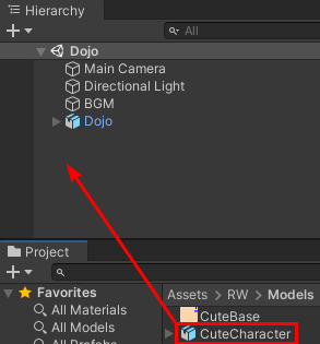
To add the character, drag the CuteCharacter model from the Models folder into the Hierarchy.
Now set the rotation of CuteCharacter to (X:0, Y:180, Z:0), so it’s facing towards the camera. Next, create a new animation controller by right-clicking the RW\Animations folder and selecting Create > Animation Controller.
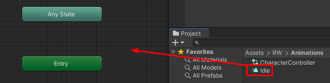
Name it CharacterController and double-click it to open the Animator window. Now drag the Idle animation from the RW\Animations folder onto the Animator grid to make it the default animation.
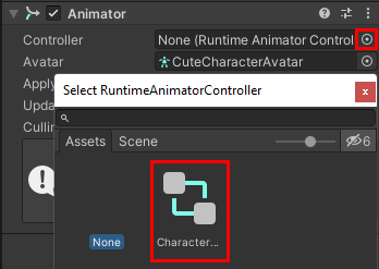
Next, select CuteCharacter in the Hierarchy and click the selector button next to the Controller field. Select CharacterController in the selection window.
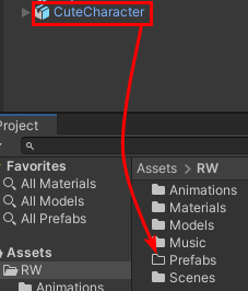
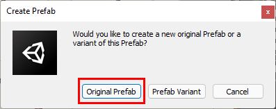
As a final step, you’ll need to attach the weapon the character’s right hand. To do this, start off by make the character into a prefab by creating a new Prefabs folder in the Assets/RW folder and dragging CuteCharacter to it.
A popup will appear asking you what type of prefab you want to create, select Original Prefab here.
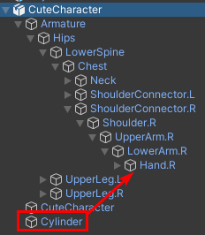
Now double click the CuteCharacter prefab you just created to open it in Prefab Mode. Expand CuteCharacter in the Hierarchy and drag Cylinder to Hand_R to parent it. This is the limitation of adding a separate object as I discussed earlier. Not doing this will result in the weapon just floating around the character.
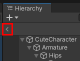
Now exit Prefab Mode by clicking the arrow button below the + button at the top left of the Hierarchy.
That’s it! Press the play button to see the character in motion.
Now press the play button again to stop the scene and press CTRL + S to save the changes you’ve made.
Where to Go From Here?
Congratulations on finishing this tutorial. You can download the final project using the link at the top or bottom of this tutorial.
In this tutorial, you learned how to:
- Create an armature (skeleton) for a character and rig it
- Modify the character with accessories and objects
- Export to FBX
- Import Blender models
- Create and tweak a humanoid avatar
- Attach objects to a character
- Animate a humanoid in Unity
To use the knowledge you’ve gained, you can create some accessories yourself and give them a different color or pattern. If you know some modeling, you can also create a character from scratch and rig it.
To learn more about Blender, check out these tutorials:
To learn more about Mecanim and the Avatar system, read this blog post by Unity.
Thanks so much for reading this tutorial to the end. If you have any questions or comments, feel free to join the discussion below.
raywenderlich.com Weekly
The raywenderlich.com newsletter is the easiest way to stay up-to-date on everything you need to know as a mobile developer.
Get a weekly digest of our tutorials and courses, and receive a free in-depth email course as a bonus!
Recommend
About Joyk
Aggregate valuable and interesting links.
Joyk means Joy of geeK