

使用 SUMO 进行仿真(2)-Node 和 Edge
source link: https://mathpretty.com/12797.html
Go to the source link to view the article. You can view the picture content, updated content and better typesetting reading experience. If the link is broken, please click the button below to view the snapshot at that time.

使用 SUMO 进行仿真(2)-Node 和 Edge
摘要本文是 SUMO 进行仿真的第二篇。主要详细的介绍 Node 和 Edge 这两个文件类型(详细了解一下这两个文件的组成,如何生成 Network),通过这两个文件来生成 Network。
这是使用 SUMO 来进行仿真的第二篇内容。在上一篇的例子中,我们使用 SUMO 完成了一个简单的例子,了解了 node 和 edge 文件,并制作了一个简单的路网。这一篇会就上面的问题进行展开,进一步了解 node 和 edge 文件(我们会创建一个稍微复杂的环境)。
Network的创建,关于node和edge的用法;- Edge Type 的使用,设置 edge 的属性,来简化 edge 文件;
- Road Access Permissions(规定道路允许通行的车辆);
- 知乎上关于 sumo 的一个教程文章, 还是很不错的:
- 本文的相关代码参考 Github 仓库,SUMO Tutorial(
Node_Edge_Introduce文件夹部分)
Network 文件生成
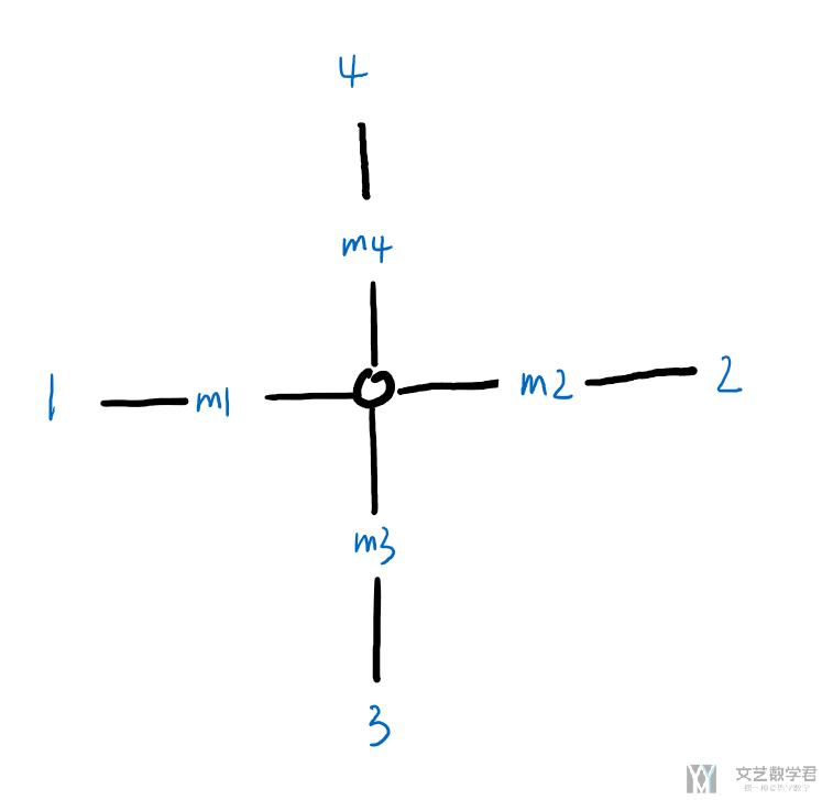
这一部分参考自,Networks/PlainXML。首先我们创建 net.xml。整个 network 的结构如下所示,共有 9 个节点(中心节点+周围的 8 个节点):
Node 的相关说明 (Node Descriptions)
按照上面的示意图,我们新建 ".nod.xml" 来描述上面的路网结构。完整文件如下所示:
- <nodes> <!-- The opening tag -->
- <node id="0" x="0.0" y="0.0" type="traffic_light"/> <!-- def. of node "0" -->
- <node id="1" x="-500.0" y="0.0" type="priority"/> <!-- def. of node "1" -->
- <node id="2" x="+500.0" y="0.0" type="priority"/> <!-- def. of node "2" -->
- <node id="3" x="0.0" y="-500.0" type="priority"/> <!-- def. of node "3" -->
- <node id="4" x="0.0" y="+500.0" type="priority"/> <!-- def. of node "4" -->
- <node id="m1" x="-250.0" y="0.0" type="priority"/> <!-- def. of node "m1" -->
- <node id="m2" x="+250.0" y="0.0" type="priority"/> <!-- def. of node "m2" -->
- <node id="m3" x="0.0" y="-250.0" type="priority"/> <!-- def. of node "m3" -->
- <node id="m4" x="0.0" y="+250.0" type="priority"/> <!-- def. of node "m4" -->
- </nodes> <!-- The closing tag -->
在上面的例子中,id 为 0 的节点是整个十字路口的中心节点,也是红绿灯。可以看他的 type 是 traffic_light,表示这个 node 是信号灯。 于是整个 node 的关系如下图所示(和上面的结构是一样的):
Edge 的相关说明 (Edge Descriptions)
在有了上面的 Node 的定义之后,下面需要定义 Edge。下面是一个基础的 Edge 文件的定义,对于每一个 edge 来说,最基础的是需要包含:
- id, 每一个 edge 独特的标志, 用来找到指定的 edge;
- from, to,from 和 to 是与上面的 node 的 id 对应的)
- priority,优先级, 在转弯处有用;
- numLanes,这个edge上包含多少个车道;
- speed,车道的车速,也就是限速;
我们新建一个「hello.edg.xml」,并输入以下的内容:
- <edges>
- <edge id="1fi" from="1" to="m1" priority="2" numLanes="2" speed="11.11"/>
- <edge id="1si" from="m1" to="0" priority="3" numLanes="3" speed="13.89"/>
- <edge id="1o" from="0" to="1" priority="1" numLanes="1" speed="11.11"/>
- <edge id="2fi" from="2" to="m2" priority="2" numLanes="2" speed="11.11"/>
- <edge id="2si" from="m2" to="0" priority="3" numLanes="3" speed="13.89"/>
- <edge id="2o" from="0" to="2" priority="1" numLanes="1" speed="11.11"/>
- <edge id="3fi" from="3" to="m3" priority="2" numLanes="2" speed="11.11"/>
- <edge id="3si" from="m3" to="0" priority="3" numLanes="3" speed="13.89"/>
- <edge id="3o" from="0" to="3" priority="1" numLanes="1" speed="11.11"/>
- <edge id="4fi" from="4" to="m4" priority="2" numLanes="2" speed="11.11"/>
- <edge id="4si" from="m4" to="0" priority="3" numLanes="3" speed="13.89"/>
- <edge id="4o" from="0" to="4" priority="1" numLanes="1" speed="11.11"/>
- </edges>
这里每一个 edge 包含多个 lane (车道,通过参数「numLanes」进行设置)。我们以上面的 node 0, node m4, node 4 这三个 node 之间的 edge 作为例子来进行简单的说明. 他们整体的车道关系如下所示:
- 从
node 4到node m4方向, 有 2 个车道; - 从
node m4到node 0方向, 有 3 个车道; - 从
node 0到node 4方向, 有 1 个车道;
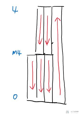
所以他们上面 edge 的关系如下所示,这里设置的车道数与上面解释的是一样的:
- <edge id="4fi" from="4" to="m4" priority="2" numLanes="2" speed="11.11"/> <!-- 4->m4, 2 车道 -->
- <edge id="4si" from="m4" to="0" priority="3" numLanes="3" speed="13.89"/> <!-- m4->0, 3 车道 -->
- <edge id="4o" from="0" to="4" priority="1" numLanes="1" speed="11.11"/> <!-- 0->4, 1 车道 -->
在有了 node 和 edge 之后,我们就可以生成 network 文件了。我们通过下面的命令进行生成:
- netconvert --node-files=hello.nod.xml --edge-files=hello.edg.xml --output-file=hello.net.xml
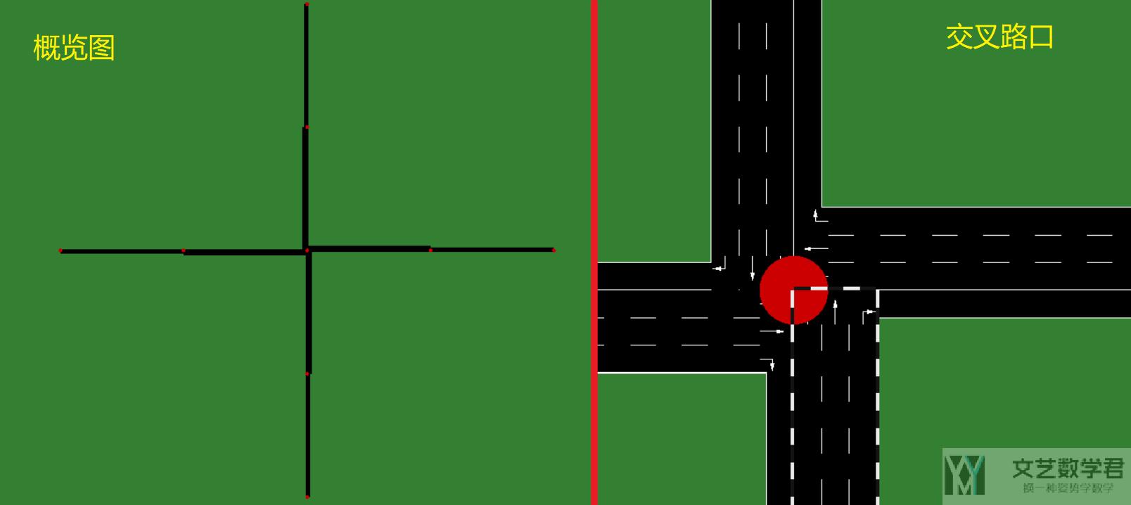
成功运行上面的命令后,会生成 hello.net.xml 文件。我们使用 NetEdit 打开该文件,可以看到如下所示的路网结构,与上面我们介绍的结构是一样的:
Edge Type
上面我们对于每一个 edge 是单独设置他的属性的。可以看到其中有些属性是重复的,所以我们可以先定义 edge type,接着将 edge type 用在每一个 edge 上面。我们将 edge type 存储在 cross3l.typ.xml 的文件中,如下所示:
- <types>
- <type id="a" priority="3" numLanes="3" speed="13.889"/>
- <type id="b" priority="2" numLanes="2" speed="11.111"/>
- <type id="c" priority="1" numLanes="1" speed="11.111"/>
- </types>
接着定义 edge 文件。该文件还是保存为 cross3l.edg.xml 文件。 所有 edge 的类型通过 type 来进行定义(这里就不需要说明每一个 edge 的 「numLanes」、「speed」等属性了):
- <edges>
- <edge id="1fi" from="1" to="m1" type="b"/>
- <edge id="1si" from="m1" to="0" type="a"/>
- <edge id="1o" from="0" to="1" type="c"/>
- <edge id="2fi" from="2" to="m2" type="b"/>
- <edge id="2si" from="m2" to="0" type="a"/>
- <edge id="2o" from="0" to="2" type="c"/>
- <edge id="3fi" from="3" to="m3" type="b"/>
- <edge id="3si" from="m3" to="0" type="a"/>
- <edge id="3o" from="0" to="3" type="c"/>
- <edge id="4fi" from="4" to="m4" type="b"/>
- <edge id="4si" from="m4" to="0" type="a"/>
- <edge id="4o" from="0" to="4" type="c"/>
- </edges>
之后我们在生成 cross3l.net.xml 的时候, 只需要加上cross3l.typ.xml文件即可。我们还是使用 netconvert 来生成最终的 netfile。
- netconvert --node-files=cross3l.nod.xml --edge-files=cross3l.edg.xml --type-files=cross3l.typ.xml --output-file=cross3l.net.xml
Road Access Permissions
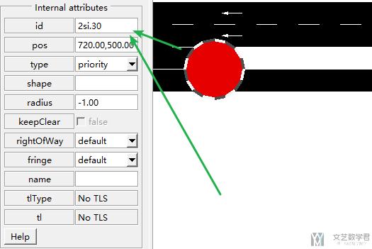
我们还可以对其中某个 edge 其中的 lane 进行额外的设置。例如可以定义 disallow 和 allow。当disallow='all' 的时候,这个可能表示是绿化带等,不能通行。这里 disallow 和 allow 后面接车辆的类型(list of vehicle classes)。例如可以写 disallow="passenger taxi"。
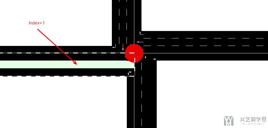
我们对上面的 cross3l.edg.xml 文件进行修改。我们修改 edge_id=1si,本来他是有三个车道的,我们将其中第二个车道设置为无法通行:
- ... previous definitions ...
- <edge id="1si" from="m1" to="0" type="a">
- <lane index="1" disallow="all"/>
- </edge>
- <edge id="1o" from="0" to="1" type="c"/>
- ... further definitions ...
上面 id='1si' 这个 edge 上,index=1(第二个 lane 上面无法通行)。最后效果如下:
参考资料,Road access permissions (allow, disallow)
Road Segment Refining
对于同一段 edge,我们可以对不同的位置来进行分别定义。例如下面的例子(一种比较常见的用法):
- ... previous definitions ...
- <edge id="2si" from="m2" to="0" priority="3" numLanes="3" speed="13.89">
- <split pos="0" lanes="0 1"/>
- <split pos="30" lanes="0 1 2" speed="10"/>
- </edge>
- ... further definitions ...
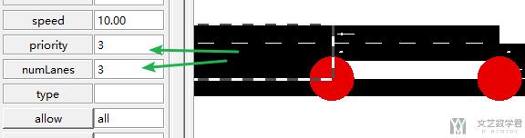
下面是按照上面的文件生成的 network。下面的 edge 有 3 个 lane。第一个 split 是从开始位置,到 0m 的位置,加一个 node(还是开始位置)。第二个 split 是从开始位置到 30m 的位置, 加一个 node (命名方式是<EDGE_ID>.<POSITION)。新增的 node 如下所示, 可以看到他的 ID 就是 edge_id+position。
node 与 node 之间只包含参数 lanes 中的 lane。例如从起点 0m 到 30m 的这一段,就只包含 2 个 lane。
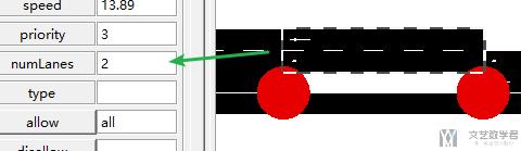
从 30m 到终点那一段, 速度就是被限制在 10, 上面 0-30 这一段速度是没有限制的. 但是这一段numLanes是=3, 因为上面 lanes="0 1 2"。
生成网格状地图
对于一些比较复杂的 network,我们就不能自己去手写 node 和 edge 文件了。下面是一个使用python 生成网格状 network 的例子(可以举一反三)。下面可以生成 node 和 edge 文件。
首先是生成 node 文件,我们会生成若干个 100100 的小方格,每一个格点就是一个 node。这里我们生成一个 66 一共 36 个 node:
- # 生成Node文件, 从左下角(0,0)开始生成的
- with open('cross.nod.xml', 'w') as file:
- file.write('<nodes> \n')
- for i in range(6):
- for j in range(6):
- file.write('<node id="node%d" x="%d" y="%d" type="priority" /> \n' %(i*6+j, i*100, j*100))
- file.write('</nodes> \n')
接着我们生成 edge 文件,我们需要将上面的 36 个 node 连接起来。这里所有的 edge 都是由两个 Lane 组成,速度都是 40。
- # 生成edge文件
- with open('cross.edg.xml', 'w') as file:
- file.write('<edges> \n')
- for i in range(6):
- for j in range(6):
- if i > 0:
- file.write('<edge id="edge%d_%d" from="node%d" to="node%d" priority="75" numLanes="2" speed="40" /> \n' % (i*6+j,k,i*6+j,(i-1)*6+j))
- k=k+1
- if i < 5:
- file.write('<edge id="edge%d_%d" from="node%d" to="node%d" priority="75" numLanes="2" speed="40" /> \n' % (i*6+j,k,i*6+j,(i+1)*6+j))
- k=k+1
- if j > 0:
- file.write('<edge id="edge%d_%d" from="node%d" to="node%d" priority="75" numLanes="2" speed="40" /> \n' % (i*6+j,k,i*6+j,i*6+j-1))
- k=k+1
- if j < 5:
- file.write('<edge id="edge%d_%d" from="node%d" to="node%d" priority="75" numLanes="2" speed="40" /> \n' % (i*6+j,k,i*6+j,i*6+j+1))
- k=k+1
- file.write('</edges> \n')
之后通过 netconvert 来生成 network 文件.
- netconvert --node-files=cross.nod.xml --edge-files=cross.edg.xml --output-file=cross.net.xml
最后生成的 network 如下所示:

Network 文件说明
下面简单介绍一下生成的 network 文件。在生成的 network 中, 会包含 direction,下面是一些缩写与全称的对应关系。
- “s” = straight
- “t” = turn
- “l” = left
- “r” = right
- “L” = partially left
- “R” = partially right
- “invalid” = no direction
- 微信公众号
- 关注微信公众号
-

- QQ群
- 我们的QQ群号
-

Recommend
-
10
Support Mozilla (@SUMO_Mozilla)Don’t miss what’s happeningPeople on Twitter are the first to know.
-
11
Proton/MR1 Tagging Plan across channels Hey everybody, The next major release is just around the corner with Firefox 89 scheduled to be released on June...
-
10
June 10 release notes: AWS ECS Anywhere, Sumo Logic, & more!We regularly ship updates across the Pulumi ecosystem, with a release of the Pulumi CLI every two wee...
-
7
摘要本文会介绍 SUMO。主要是从 node 和 edge 文件开始,一步一步新建 network,route,最后完整路网和车流的生成。 这一篇会简单介绍一下 SUMO 使用的整个流程,来进行快速入门 SUMO。包括 node 和 edge 文件的介绍。同时介绍 NetEdit 的...
-
5
3 reasons why your team needs a sumo wrestler And a few why you maybe don't...
-
7
使用 SUMO 进行仿真(4)-信号灯(Traffic Light) 2021年9月26日07:09:05
-
11
摘要在本文中我们会着重介绍了车流的生成。包括生成车流的方式,也会介绍 route 文件的相关内容。生成车流的方式包括直接修改 route 文件,通过 flow 指定起点和终点,通过 trip 同时生成多辆车。 在前面的两篇文章中,我们着重介绍了路网...
-
3
使用 SUMO 进行仿真(5)-Detectors 介绍 2021年11月3日07:53:34
-
10
Sumo Logic muscles-up for CircleCI & GitLab Adrian Bridgwater Published: 22 November 2021 12:01
-
7
SUMo 5.14.12 Download SUMo, which stands for Software Update Monitor. Thanks to SUMo you'll be able to keep your PC up-to-date by using the most recent version of your favorite software ! Unlike build-in auto update features, SUMo tel...
About Joyk
Aggregate valuable and interesting links.
Joyk means Joy of geeK