

Ohm? Don’t Forget Kirchhoff!
source link: https://hackaday.com/2017/05/25/ohm-dont-forget-kirchhoff/
Go to the source link to view the article. You can view the picture content, updated content and better typesetting reading experience. If the link is broken, please click the button below to view the snapshot at that time.
It is hard to get very far into electronics without knowing Ohm’s law. Named after [Georg Ohm] it describes current and voltage relationships in linear circuits. However, there are two laws that are even more basic that don’t get nearly the respect that Ohm’s law gets. Those are Kirchhoff’s laws.
In simple terms, Kirchhoff’s laws are really an expression of conservation of energy. Kirchhoff’s current law (KCL) says that the current going into a single point (a node) has to have exactly the same amount of current going out of it. If you are more mathematical, you can say that the sum of the current going in and the current going out will always be zero, since the current going out will have a negative sign compared to the current going in.
You know the current in a series circuit is always the same, right? For example, in a circuit with a battery, an LED, and a resistor, the LED and the resistor will have the same current in them. That’s KCL. The current going into the resistor better be the same as the current going out of it and into the LED.
This is mostly interesting when there are more than two wires going into one point. If a battery drives 3 magically-identical light bulbs, for instance, then each bulb will get one-third of the total current. The node where the battery’s wire joins with the leads to the 3 bulbs is the node. All the current coming in, has to equal all the current going out. Even if the bulbs are not identical, the totals will still be equal. So if you know any three values, you can compute the fourth.
If you want to play with it yourself, you can simulate the circuit below.
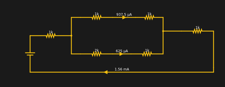
The current from the battery has to equal the current going into the battery. The two resistors at the extreme left and right have the same current through them (1.56 mA). Within rounding error of the simulator, each branch of the split has its share of the total (note the bottom leg has 3K total resistance and, thus, carries less current).
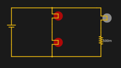
Kirchhoff’s voltage law (KVL) says that the voltage around a loop has to sum to zero. Take a simple example. A 12V battery has a 12V light bulb across it. How much voltage is across the bulb? 12V. If there are two identical bulbs they will still see 12V across each bulb.
You can simulate this circuit to see the effect. The loop with the two bulbs has 12V across it and each bulb gets half because they are identical. The right-hand path has different voltages but they still have to add up to 12.
All by itself, KVL wouldn’t be very useful, but there is a principle known as superposition. That’s a fancy way of saying that you can break a complex circuit up into pieces and look at each piece, then add the results back and get the right answer.
Analysis
You can use these two laws to analyze circuits using nodal analysis (for KCL) or mesh analysis for KVL, regardless of how complex they are. The only problem is that you wind up with lots of equations and may have to solve them as a system of simultaneous equations. Luckily, computers are really good at that, and circuit analysis software often uses one of these techniques to find answers.
Consider this circuit:
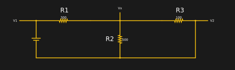
This is actually too simple since we know V1 and V2 right out of the gate (5V for the battery and 0, because V2 is connected to ground). In addition, a human would know to calculate the equivalent of R2 and R3, but that might not be apparent in a more complex circuit, especially to a computer.
The node labeled Vx has three currents. I1 is the current through the battery and R1 flowing in. I2 is the current flowing through R2 and I3 is the current flowing through R3. You can write equations for all three currents, easily:
I1=(Vx-V1)/R1

I2=(Vx-V2)/R2

I3=(Vx-V2)/R3
Of course, we know the values of everything on the right except Vx, so:
I1=(Vx-5)/300

I2=Vx/R2

I3=Vx/R3
Note that the first line above is “backward” because I1 is flowing into node Vx and the others are flowing out; there are several ways you could elect to handle this. Now using KCL we know that: I1+I2+I3=0 You can replace all of the I’s with their equation:
(Vx-5)/300 + Vx/500 + Vx/100 = 0

(5Vx+3Vx+15Vx)/1500 = 5/300

23Vx/1500=5/300

23Vx=1500(5/300)

Vx=25/23=1.09V (about)
For line 2 above, the least common multiple of 300, 500, and 100 is 1500 and we add 5/300 to both sides to get the Vx terms alone. In line 4 we multiply both sides by 1500 to arrive at the solution.
If you look at the simulation, you will see that Vx is 1.09V. Now you can go back in the equations and get I1, I2, and I3, by just plugging in values. Of course, real problems get thornier and usually wind up with a system of equations you have to solve.
If you really want to pursue the higher math, you might enjoy the Khan Academy video on nodal analysis, below. Note that they handle the idea of negative current explicitly. If you want to use their math on our example, then I2 and I3 are explicitly negative and I1 is derived from 5-Vx instead of Vx-5. Then you wind up with -23Vx=-25 and get the same result in the end. That’s how math is.
The other way to do this sort of systematic analysis with KCL and KVL is mesh analysis. There you use superposition and simultaneous equations. But don’t worry — it isn’t as hard as it might sound. Rather than go into that, you can watch another Khan Academy video on the subject. Just dust off those algebra skills.
History
[Gustav Kirchhoff] was a German physicist who worked all this out in 1845, about 20 years after [Ohm] worked out his law. Actually, [Ohm] wasn’t first, he was just the first to talk about it. [Henry Cavendish] figured out Ohm’s law in 1781 using Leyden jars (big capacitors) and his own body as an ammeter. He’d complete the circuit with his body and judge the current flow by the amount of shock he received. Now that’s dedication. [Ohm] had a better experimental setup and — as far as we know — didn’t shock himself as a matter of course.
You might think that [Ohm] was well respected for his discovery, but that wasn’t the case. The establishment was very upset with his findings. One German yearbook of scientific critique labeled it “a web of naked fancies.” The German Minister of Education called it a “heresy.” It was in opposition to Barlow’s law (suggested in 1825 by [Peter Barlow]) which said that current was related to the diameter of the wire and the length of it.
Actually, [Barlow] wasn’t totally wrong. He used a constant voltage and did not understand (as [Ohm] did) that the voltage source had an internal resistance. [Ohm], in fact, switched from batteries to thermocouples because at the time they had a more stable output and predictable low internal resistance.
It is hard to imagine today, but there was a lot of experimentation and law writing back then — not all of it correct, obviously. Often the person we associate with the work wasn’t really the first, just the one that published. Another example is the Wheatstone bridge. [Sir Charles Wheatstone] made it famous, but it was actually the brainchild of [Samuel Christie].
For some reason, everyone knows Ohm’s law, but you don’t hear much about poor old [Gustav]. If you take an electrical engineering class, these laws are among the first things you learn. You might not use it every day, especially in this day of computer simulations. However, understanding analysis like this can help you develop an intuitive understanding of electronics.
By the way, the simulations in this post are using the Falstad simulator we’ve covered before. While it is common to use a simulator to just give you answers, it is also useful to let it check your work. The equations above, for example, would be easy to mix up signs or make another mistake. If the answer doesn’t match the simulator, you probably made a mistake. Sure, you can just read the value off the simulator, but that doesn’t let you develop the intuition that working through the math will.
Recommend
About Joyk
Aggregate valuable and interesting links.
Joyk means Joy of geeK