

Creating Diagrams using PCB Design Software (ECAD)
source link: https://neil.computer/notes/ecad-diagrams/
Go to the source link to view the article. You can view the picture content, updated content and better typesetting reading experience. If the link is broken, please click the button below to view the snapshot at that time.

Creating Diagrams using PCB Design Software (ECAD)
Earlier last week, I stumbled upon Brandur's blog post about 'Atomic Transactions in PostgreSQL'. It was a fantastic read and I couldn't help but notice ridiculously beautiful diagrams about database transactions. These monospaced diagrams are created using a MacOS app called Monodraw. I bought the app, it was $10 and I had almost forgotten about it.
Over the weekend, I needed to draw an I/O architecture diagram for I2C bus and I fired up Powerpoint 2019 almost with muscular memory only to close it right away. Rebooted in MacOS and this new shiny app - Monodraw is waiting for me.
A few samples from the intro demo files that ships with Monodraw:
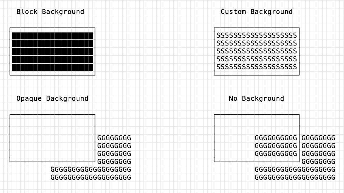 Monodraw background styles
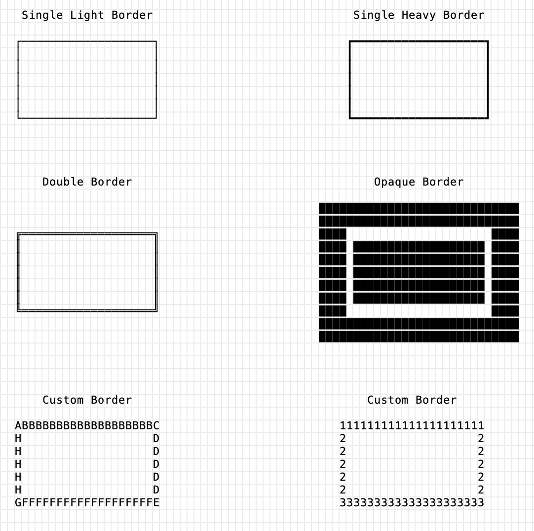 Monodraw border styles
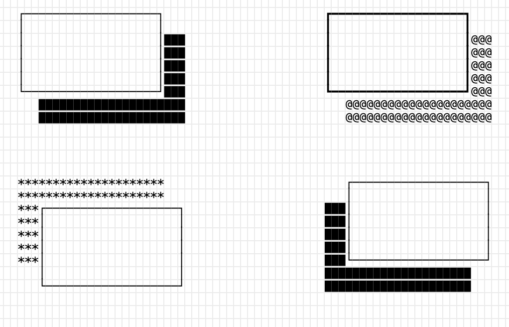 Monodraw shadow effects
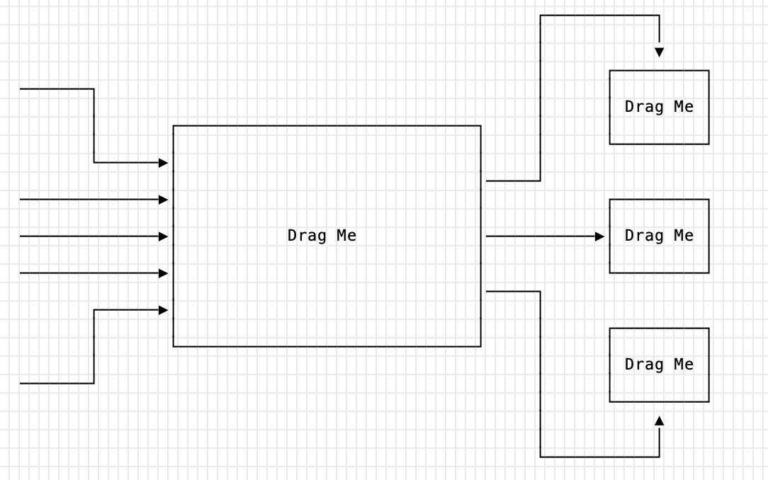 Monodraw diagram sample
It is quirky, cool and still functional. Kudos to the developers! [1]
Monodraw adds a visual, and some functional, twist to creating diagrams with Powerpoint (or even Adobe Illustrator). For example, one could share the diagram just as a .txt file or display it on a terminal. Over the weekend, I was working on a PCB schematic and something hit me.
It is really interesting to think about what ECAD software as a tool that converts logical relationship between objects (electrical components) into a 2 dimensional spatial representation - where objects are connected to each other using nets. When we think of creating diagrams, we are essentially thinking about how various key objects relate to other. The semiotics are similar to a PCB Schematic, but not exactly. PCB Schematics have tailor made features for what it is good at - designing PCBs. Is it possible to create non-electronic schematics and diagrams with ECAD software? Why not? Overkill? Yes. Better than anything else? Yes, I reluctantly think so (at the expense of time :-)).
Monodraw
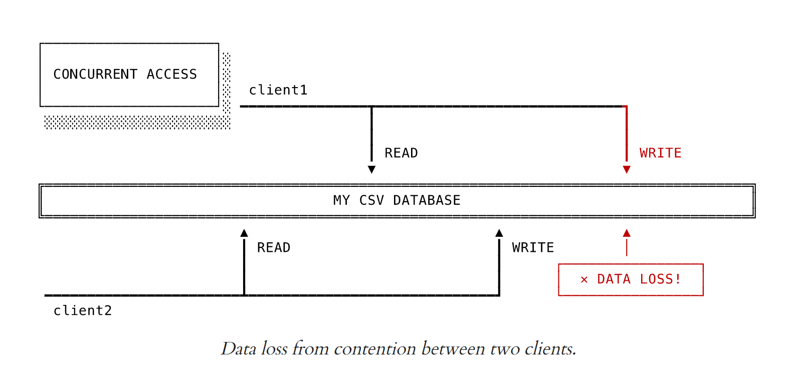
Here is one of the Brandur's diagrams. We will use it as a reference and try to understand the differences, advantages, and disadvantages of creating diagrams with an ECAD software.
Powerpoint
First, let's see what our old friend, Powerpoint can do without trying to match the aesthetics.
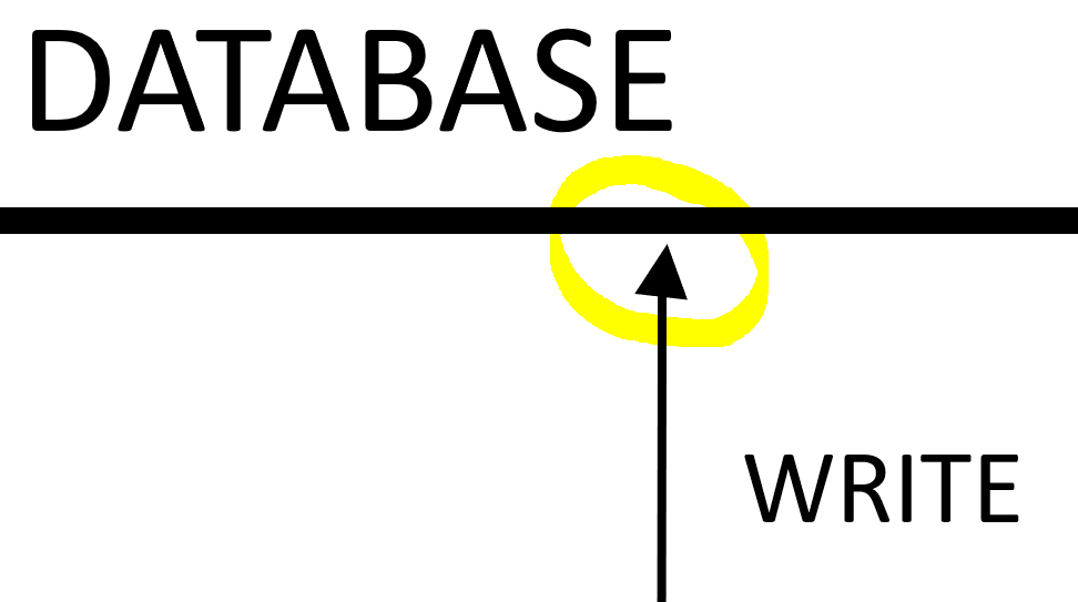
Arrow alignment doesn't snap unless it is anchored to an object. However, an arrow can only be anchored to the midpoint of any of the sides, not at arbitrary locations on the border. So you get issues like this:
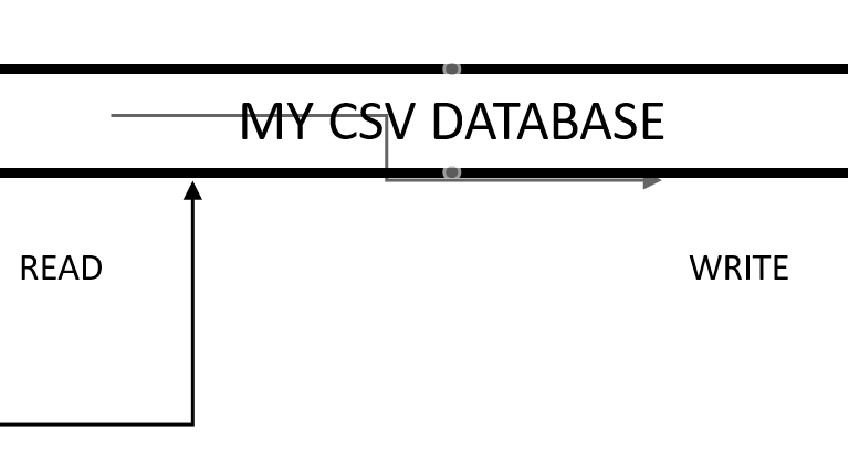
Also, every time I move the endpoint of an unanchored line, it resets to its horizontal default layout:
It is as if diagrams were an afterthought in Powerpoint and everything is clunky. I don't know how to describe it. It is akin to launching Sublime Text vs. Eclipse. Eclipse feels heavy.
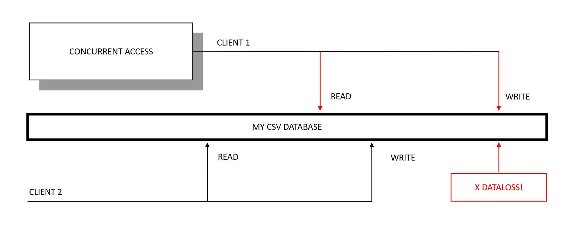
But, after some pain (and previous practice at a bureaucratic corporate institution), one can come up with something like the following in Powerpoint. Close enough sans monospaced goodness.
Let's see how we can do this in an ECAD software (such as Altium). First, create a component for each object. A component is one of the fundamental objects in schematic design (along with a net). It creates an abstraction of any device - a discrete device such as a resistor to a full SIP (system-in-package) device such as the TI RF430F5978.
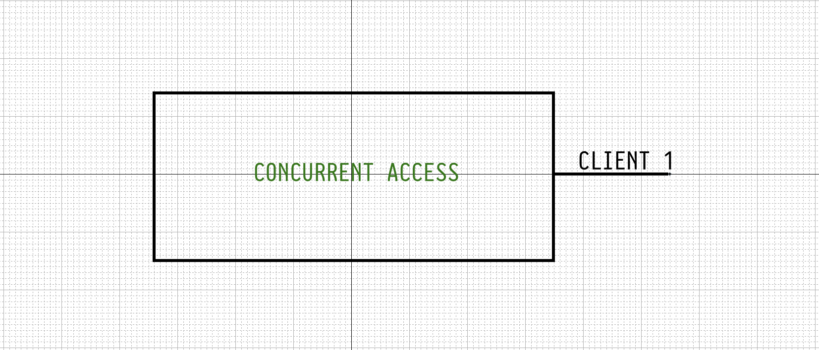
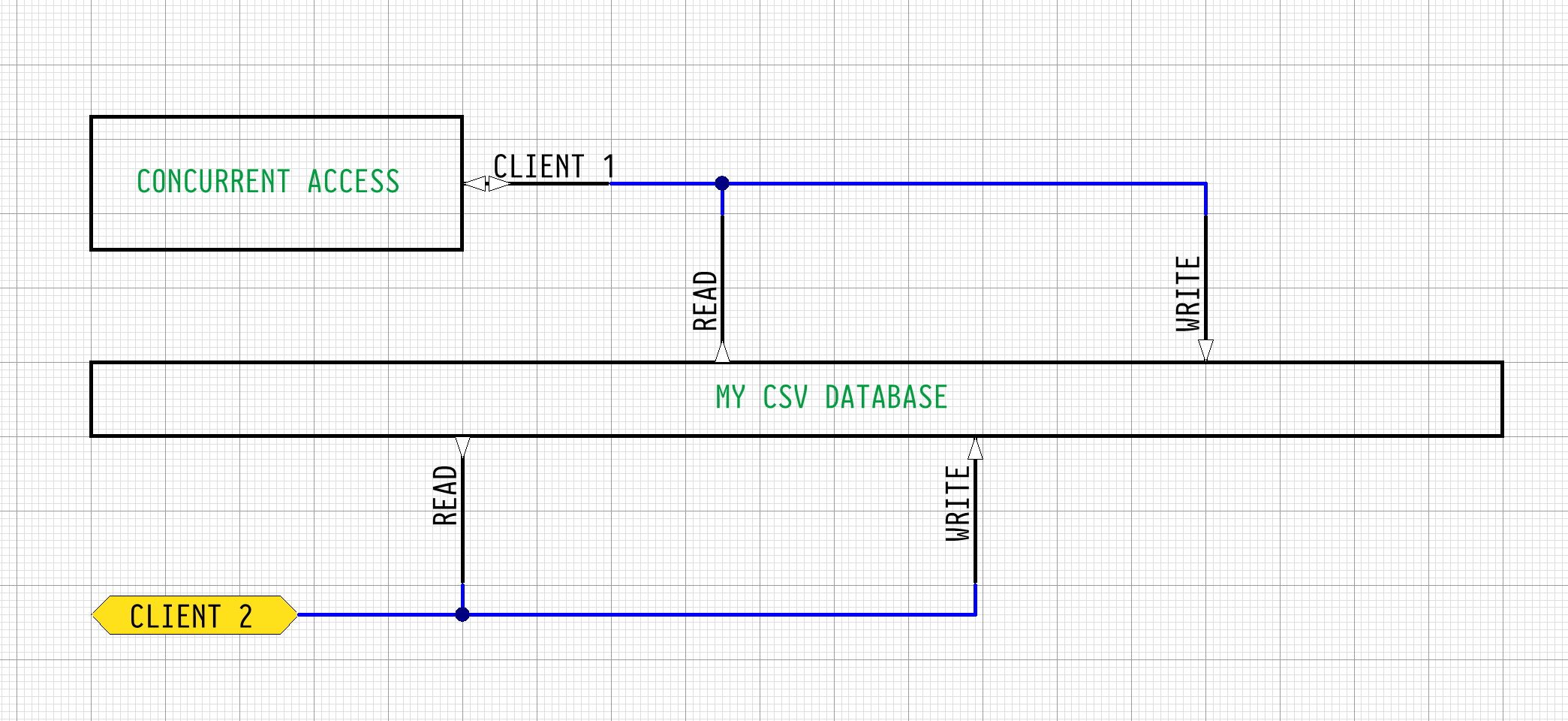
In this case, CONCURRENT ACCESS , MY CSV DATABASE, and X DATALOSS! is a component, although the latter can be debated whether it should be a text-label.
This is what it looks like in the Schematic Library.
Once it is placed on the Schematic Diagram, it gets a Designator (magenta) and optionally, a Comment (blue) assigned to it.
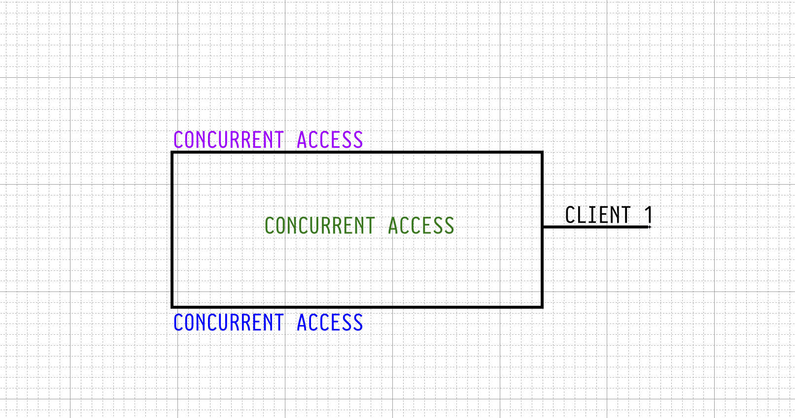
The obvious redundancy is a product of my setup (hidden Designator and Comment in Schematic Library) and placing a text box (green) for the centered label. There is a better way. We can omit the text label (green) and the Comment (blue) and only keep the Designator. Designators can even be programmatically created by appending with a ?, for example, CONCURRENT ACCESS? which would iterate over as CONCURRENT ACCESS1, CONCURRENT ACCESS2, etc.
Similarly, create MY CSV DATABASE component and connect everything with wires.
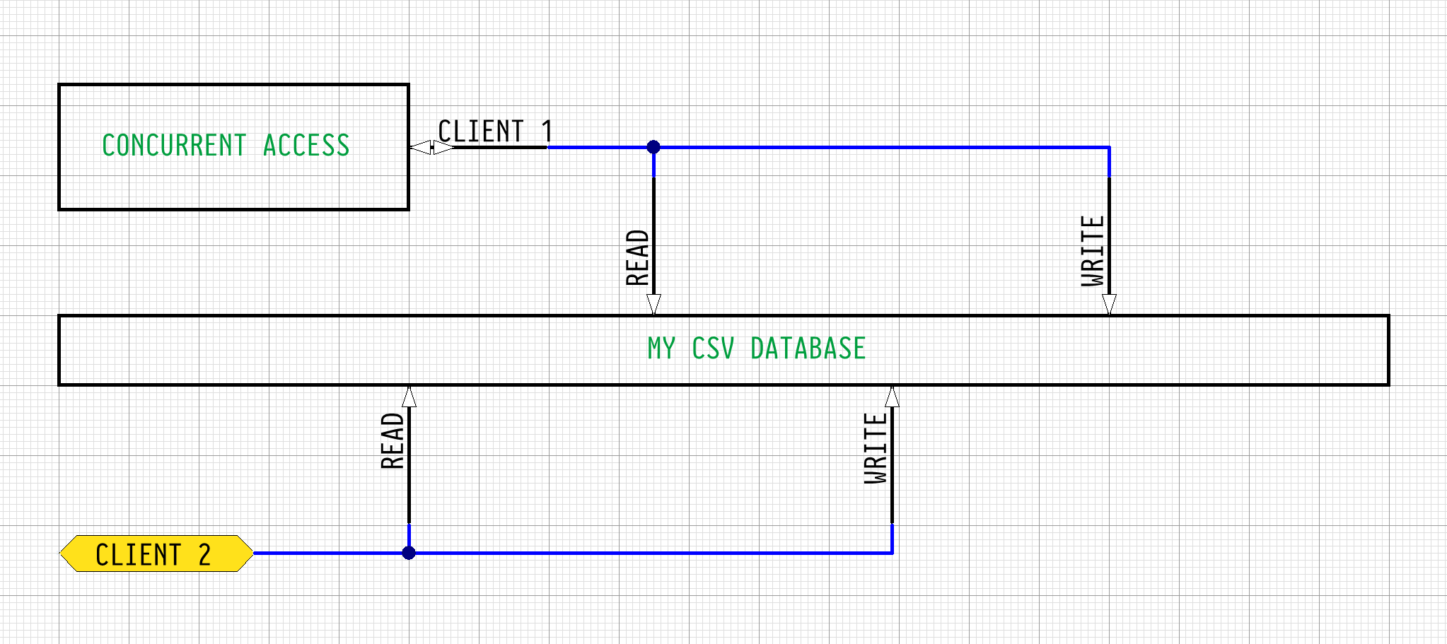
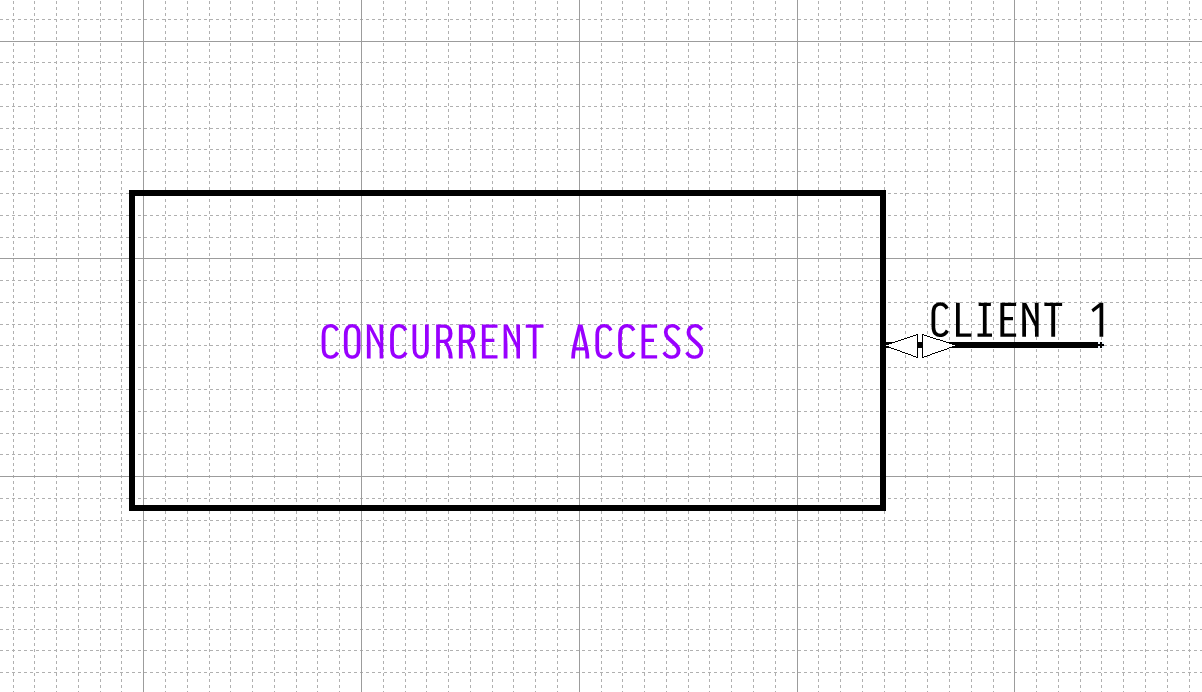
A few things to notice - CLIENT 2 is kind of like a net-label. It connects two pins without a physical wire. However, it is not just a net-label, it is a Port in this case because CLIENT 2 is presumably, without knowing the context, connected to another CONCURRENT ACCESS component somewhere off the viewport. This second component must be connected off of the viewport or the DRC (Design Rule Checking won't be happy). You could say this is going too far with creating diagrams but there is something we found through the same DRC system. Read should be an output pin of MY CSV DATABASE because the CLIENT 1 pin, that it is connected to, is an I/O pin (not just Output).
Let's correct this (pardon me if my assumption is incorrect, I don't know the context of this diagram).
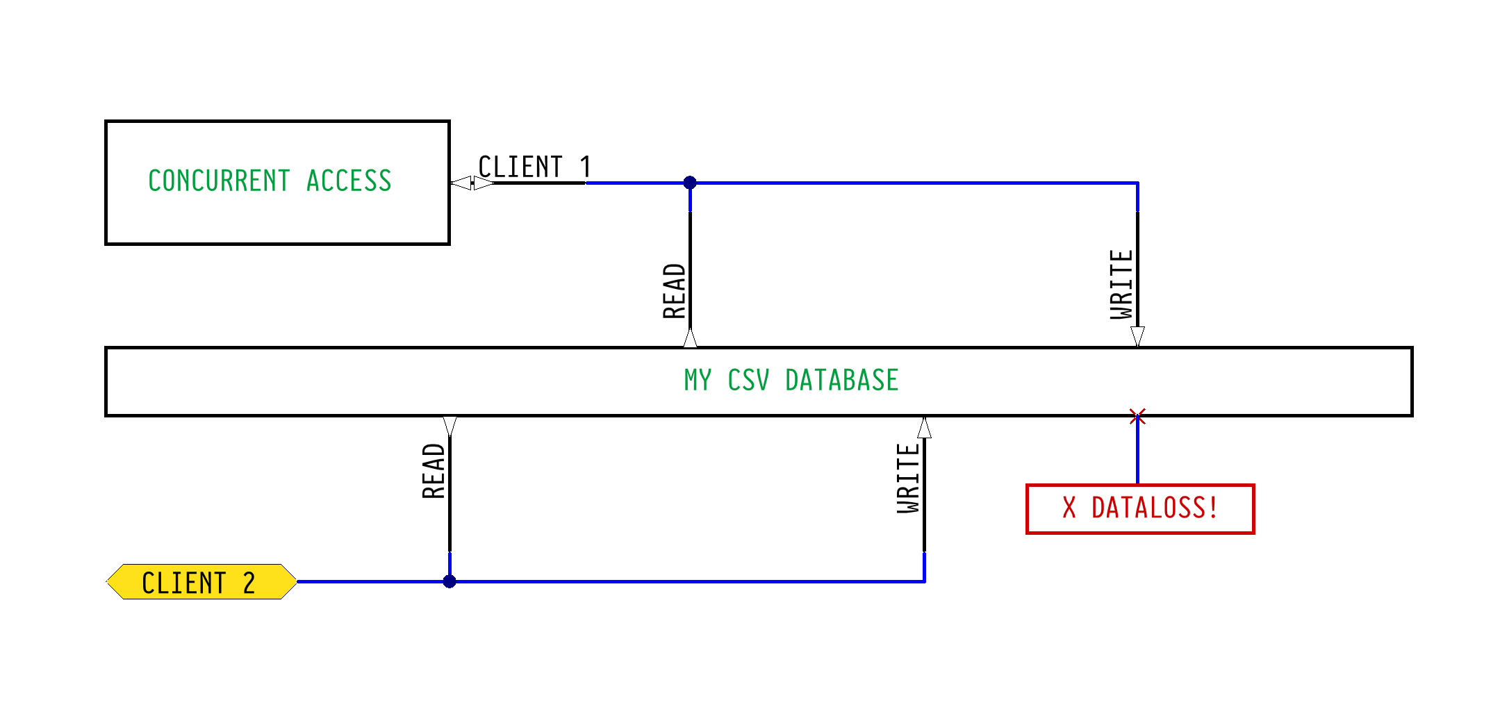
And finally, we can add the warning label X DATALOSS! ,
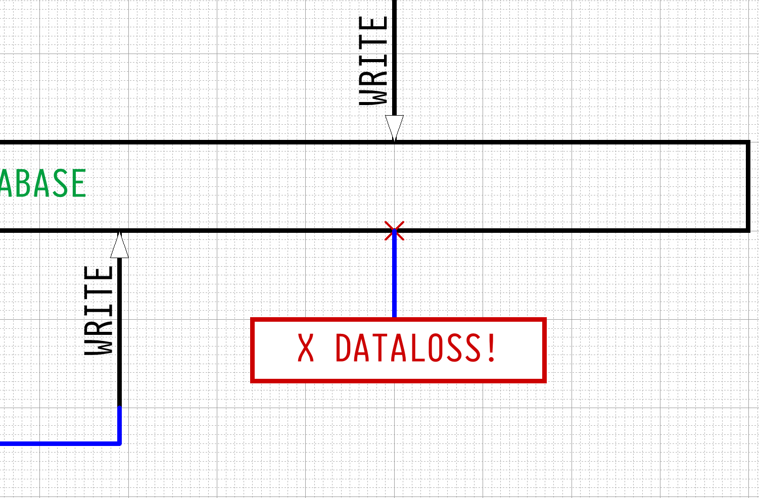
X DATALOSS! warning.Turn off the alignment grid and voila! we have a really weird way of creating diagrams.
PCB schematics is a rigid, inappropriate and strangely a fun way to create diagrams! It is time-consuming, has somewhat of a learning curve and it can be potentially expensive. But diagrams are oh so beautiful! For most needs, Monodraw hits a sweet spot - brutalist, functional and quirky (and dare I say, aesthetic?).
References:
[1] One of the Monodraw developers, Milen, also created the infamous minimalist to-do list app called Clear.
Notes:
[1] I use Pragmata Pro for engineering schematics as it is condensed, monospaced and has many technical features (such as slashed zero, symbols, etc.).
Recommend
About Joyk
Aggregate valuable and interesting links.
Joyk means Joy of geeK