

Plan 9 on epaper (SPI driver)
source link: https://boxbase.org/entries/2021/jan/1/plan9-on-epaper/
Go to the source link to view the article. You can view the picture content, updated content and better typesetting reading experience. If the link is broken, please click the button below to view the snapshot at that time.

Plan 9 on epaper (SPI driver)
Before the holidays I bought an 7.8 inch e-paper display from waveshare that connects to raspberry pi. It cost about 150$, but the specs are decent enough. It's definitely good enough for an e-book reader.
Resolution: 1872x1404 16-color grayscaleRefresh time: 450msDot pitch: 0.0845mm x 0.0854mm (300.6 PPI)
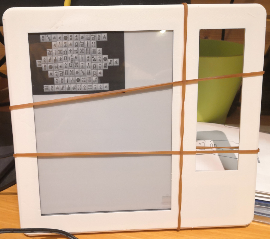
I wrote a driver to run Plan 9 terminal on this display. On the picture it's running 'games/mahjongg'. I got the serial peripheral interface driver to run fast enough that you could comfortably use this screen.
The visual stability in Plan 9 user interface makes it a good operating system for driving slow-framerate e-paper displays.
There's few obstacles before I can demonstrate this properly, I'll write about those later in this post. For now, lets go through the details.
Resources
I relied on the following resources to write the driver:
- Plan 9 manual pages and the kernel source code.
- Waveshare's datasheets, documents and demonstration code for their hardware.
- BCM2835 ARM peripherals datasheet.
I feel like I was missing one or two essential manuals, but other than that I think this was enough to get it done.
How it was made
I'm going to present the changes in a sensible order. It's not the order where the code was developed in though.
I started by loading Richard Miller's 'spi.c' and 'devspi.c', I drove the SPI-interface from the userspace at first, then I wrote my own 'devit8951.c' -driver that I can access from the userspace. After I had something working, only then I went and modified the 'spi.c', 'dma.c' and finally rewrote the 'screen.c'.
I knew how to modify and recompile a kernel. There's a debugger and I recall reading that it's neat.
Likewise a disclaimer is worthwhile: I don't know anything about how this should be done. I just poked and read around, and got results.
Changes to the DMA driver
Direct memory access is piece of hardware aside CPU, copying bytes in/out from the system memory. Kernel leaves notes for the DMA controller, and the DMA controller interrupts the kernel when it finishes copying a note.
Richard Miller's SPI driver is rudimentary and only doing DMA. Upon trying the driver I found out it's able to transfer at most 32 bytes at once. However other drivers do not even engage the DMA on SPI unless there's more than 96 bytes to transfer.
After few hours of headscratching I figured out that I have to give a flag that tells the dma controller to wait for AXI write response to disallow writes from being stacked into the AXI bus pipeline. But giving this flag otherwise would slow things down, so it is only needed on SPI transfers.
The SPI driver must issue a read for every write request. I didn't get nil address writes/reads to work without giving src/dst ignore flags.
Here's the procedure to start the dma transfer. I'm going to pinpoint where the code was modified and how.
voiddmastart(int chan, int dev, int dir, void *src, void *dst, int len){Ctlr *ctlr;Cb *cb;int ti;ctlr = &dma[chan];if(ctlr->regs == nil){ctlr->regs = (u32int*)(DMAREGS + chan*Regsize);ctlr->cb = xspanalloc(sizeof(Cb), Cbalign, 0);assert(ctlr->cb != nil);dmaregs[Enable] |= 1<<chan;ctlr->regs[Cs] = Reset;while(ctlr->regs[Cs] & Reset);intrenable(IRQDMA(chan), dmainterrupt, ctlr, BUSUNKNOWN, "dma");}ctlr->len = len;cb = ctlr->cb;ti = 0;switch(dir){case DmaD2M:ctlr->flush = dst;
This condition block was introduced to add the Destignore -flag when a nil address is supplied.
if(dst==nil){ti = Srcdreq | Destignore;}else{dmaflush(1, dst, len);ti = Srcdreq | Destinc;}cb->sourcead = dmaioaddr(src);cb->destad = dmaaddr(dst);break;case DmaM2D:ctlr->flush = nil;
Here's another one for the source address, in case we do writes that need to supply nulls.
if(src==nil){ti = Destdreq | Srcignore;}else{dmaflush(1, src, len);ti = Destdreq | Srcinc;}cb->sourcead = dmaaddr(src);cb->destad = dmaioaddr(dst);break;case DmaM2M:ctlr->flush = dst;dmaflush(1, dst, len);dmaflush(1, src, len);ti = Srcinc | Destinc;cb->sourcead = dmaaddr(src);cb->destad = dmaaddr(dst);break;}
Finally here's a condition block to introduce Waitresp and disable interrupt if the dma channel is for the SPI transfer.
if(chan==DmaChanSpiTx){cb->ti = ti | dev<<Permapshift | Waitresp;}else{cb->ti = ti | dev<<Permapshift | Inten;}cb->txfrlen = len;cb->stride = 0;cb->nextconbk = 0;dmaflush(1, cb, sizeof(Cb));ctlr->regs[Cs] = 0;microdelay(1);ctlr->regs[Conblkad] = dmaaddr(cb);DBG print("dma start: %ux %ux %ux %ux %ux %ux\n",cb->ti, cb->sourcead, cb->destad, cb->txfrlen,cb->stride, cb->nextconbk);DBG print("intstatus %ux\n", dmaregs[Intstatus]);dmaregs[Intstatus] = 0;ctlr->regs[Cs] = Int;microdelay(1);coherence();DBG dumpdregs("before Active", ctlr->regs);ctlr->regs[Cs] = Active;DBG dumpdregs("after Active", ctlr->regs);}
I don't like about these changes because they introduce condition blocks that are only required for driving something through SPI.
SPI driver
In the 'spi.c' driver, I actually didn't do much anything interesting. It originally wrote to the memory location it read from. I split it into two.
voidspirw(uint cs, void *wbuf, void *rbuf, int len){Spiregs *r;int mode;assert(cs <= 2);assert(len < (1<<16));qlock(&spi.lock);if(waserror()){qunlock(&spi.lock);nexterror();}if(spi.regs == 0)spiinit();r = spi.regs;mode = r->cs & (Cpha | Cpol);r->cs = Dmaen | Adcs;
Well here's a thing I changed. I did peek at the datasheet and concluded that this code was valid. However I think this felt more like what the datasheet proposes: Activate the DMA transfer, then give the first 4 bytes directly. These first 4 bytes is a command for the SPI controller that tells how many bytes it needs to read. It can be also given in the dma transfer itself.
r->data = (len << 16) | (cs << Csshift) | Rxclear | Txclear | Ta | mode;//r->dlen = len;//r->cs = (r->cs & (Cpha | Cpol)) | (cs << Csshift) | Rxclear | Txclear | Dmaen | Adcs | Ta;/** Start write channel before read channel - cache wb before inv*/dmastart(DmaChanSpiTx, DmaDevSpiTx, DmaM2D,wbuf, &r->data, len);dmastart(DmaChanSpiRx, DmaDevSpiRx, DmaD2M,&r->data, rbuf, len);if(dmawait(DmaChanSpiRx) < 0)error(Eio);//cachedinvse(rbuf, len); this is already done.r->cs &= (Cpha | Cpol);qunlock(&spi.lock);poperror();}
I recall reading that BCM allows you to chain the dma calls. I don't need that feature, as you soon see why.
Screen driver
Each Plan 9 terminal has an exactly one screen. The e-paper display replaces the system that'd otherwise draw to the HDMI screen.
It's possible to resize the display. I know because 'aux/vga' -command can change the screen resolution.
The following 'screen.c' interacts with the 'devdraw.c' to provide a screen. Drawing driver itself is portable, same across platforms.
#include "u.h"#include "../port/lib.h"#include "mem.h"#include "dat.h"#include "fns.h"#define Image IMAGE#include <draw.h>#include <memdraw.h>#include <cursor.h>#include "screen.h"
The gscreen -is accessed from the 'devmouse.c', therefore it needs to be visible outside this file. I was wondering how that happens, but of course it's like this.
I provide some pin mappings here to configure the communication with the display.
I also provide the display width/height here, because I also need to provide the driving voltage. It's weird because the 'devinfo' provides the dimensions but not the driving voltage. Meh, I guess somebody just messed something up there.
Memimage *gscreen;#define PIN_CE0 8#define PIN_HRDY 24#define PIN_RESET 17#define SPI0_MISO 9#define SPI0_MOSI 10#define SPI0_SCLK 11#define FUNC_IN 0#define FUNC_OUT 1#define FUNC_ALT0 4#define SWIDTH 1872#define SHEIGHT 1404#define VCOM 1500#define DEVINFO_SIZE 40static u8int devinfo[DEVINFO_SIZE];
The e-paper uses some other protocol but drives it with the SPI controller. This other protocol requires that we wait for HRDY -pin to flip 1 before we send a message.
static voidwaithrdy(void){while(gpioin(PIN_HRDY) != 1);}static voidwritecmd(long cmdcode){u8int data[4] = { 0x60, 0x00, cmdcode >> 8, cmdcode };waithrdy();gpioout(PIN_CE0, 0);spirw(0, &data[0], nil, 2);waithrdy();spirw(0, &data[2], nil, 2);gpioout(PIN_CE0, 1);}static voidwritedata(u8int *block, ulong count){u8int data[2] = { 0x00, 0x00 };waithrdy();gpioout(PIN_CE0, 0);spirw(0, &data[0], nil, 2);waithrdy();spirw(0, block, nil, count);gpioout(PIN_CE0, 1);}static voidwriteword(long w){u8int data[2] = { w >> 8, w };writedata(data, 2);}static voidreaddata(u8int *block, ulong count){u8int data[4] = { 0x10, 0x00, 0x00, 0x00 };waithrdy();gpioout(PIN_CE0, 0);spirw(0, &data[0], nil, 2);waithrdy();spirw(0, &data[2], nil, 2);for (int i=0; i < count; i+=2){waithrdy();spirw(0, &block[i], &block[i], 2);}gpioout(PIN_CE0, 1);}static longreadword(void){u8int data[2];readdata(data, 2);return ((long)(data[0])<<8) | data[1];}
The short commands piece together into bigger commands.
static longreadreg(long address){writecmd(0x0010); // reg rdwriteword(address);return readword();}static voidwritereg(long address, long value){writecmd(0x0011); // reg wrwriteword(address);writeword(value);}static voidgetdevinfo(void){memset(devinfo, 0, DEVINFO_SIZE);writecmd(0x0302); // get dev inforeaddata(devinfo, DEVINFO_SIZE);}static longgetvcom(void){writecmd(0x0039); // vcomwriteword(0); // readreturn readword();}static voidsetvcom(long vcom){writecmd(0x0039); // vcomwriteword(1); // writewriteword(vcom);}static voidwaitdisplay(void){while(readreg(0x1224)); // LUTAFSR=0 when free}static voiddisplayarea(long x, long y, long w, long h, long mode){writecmd(0x0034); // dpy areawriteword(x);writeword(y);writeword(w);writeword(h);writeword(mode);}
The display is initialized on-demand. I did it this way because I'm not sure how to initialize the gpio/spi when the screen is supposed to be initialized. Otherwise this does as instructed in the datasheet, except that the slowed down spiclock on the "bootup" is my doing.
static init = 0;static voiddisplayinit(void){init = 1;spimode(0);spiclock(10);gpiosel(PIN_CE0, FUNC_OUT);gpiosel(PIN_RESET, FUNC_OUT);gpiosel(PIN_HRDY, FUNC_IN);// the reset signalgpioout(PIN_CE0, 1);gpioout(PIN_RESET, 0);delay(100);gpioout(PIN_RESET, 1);getdevinfo();writereg(0x0004, 0x0001); // enable I80 packed modeif (VCOM != getvcom()){setvcom(VCOM);}spiclock(100);displayarea(0, 0, SWIDTH, SHEIGHT, 0); // just to see whether anybody's home.}
The cursor manipulation controls are as they were in the original 'screen.c', they provide software cursor. Though it'd be likely better for me to provide a hardware cursor because there'd be a faster mode on this display precisely for rendering such a cursor.
voidcursoron(void){swcursorhide(0);swcursordraw(mousexy());}voidcursoroff(void){swcursorhide(0);}voidsetcursor(Cursor *curs){swcursorload(curs);}
I take the advantage of having to know the VCOM in advance, and initialize the screen here. I draw the screen rotated 90 degrees because I intend to mainly read with this thing.
I like that memimage got 4-bit grayscale images. It's almost if this thing was designed for driving e-paper displays.
voidscreeninit(void){Rectangle r = { {0, 0}, {SHEIGHT, SWIDTH} };memimageinit();gscreen = allocmemimage(r, GREY4);swcursorinit();gpiomeminit();conf.monitor = 1;}
I can also make use of the partial screen updates. This is the part that uploads the image to the display.
voidflushmemscreen(Rectangle r){int w, h, s;uchar *base;waitdisplay();// framebuffer pointerwritereg(0x020A, (((long)devinfo[6])<<8)|(long)devinfo[7]);writereg(0x0208, (((long)devinfo[4])<<8)|(long)devinfo[5]);// align the partial update to a boundary// where we don't need to shift bytes around.r.min.x = r.min.x&(~3);r.max.x = (r.max.x+3)&(~3);w = r.max.x - r.min.x;h = r.max.y - r.min.y;base = byteaddr(gscreen, r.min);writecmd(0x0021); // load img area startwriteword((1<<8)|(2<<4)|1); // format (big endian, 4bpp pixelformat, rotate 90)writeword(r.min.x);writeword(r.min.y);writeword(w);writeword(h);s = w/2;for(int j = 0; j < h; j++){writedata(base, s);base += gscreen->width*sizeof(ulong);}writecmd(0x0022); // img end// 6 : fast chitty flipping// 2 : slow but good flipdisplayarea(r.min.y, SHEIGHT-r.max.x, h, w, 2);}
This part is invoked by the 'devdraw.c'.
Memdata*attachscreen(Rectangle *r, ulong *chan, int* depth, int *width, int *softscreen){if(gscreen == nil)return nil;if(init==0)displayinit();*r = gscreen->r;*chan = gscreen->chan;*depth = gscreen->depth;*width = gscreen->width;*softscreen = 1;gscreen->data->ref++;return gscreen->data;}voidgetcolor(ulong p, ulong *pr, ulong *pg, ulong *pb){USED(p, pr, pg, pb);}intsetcolor(ulong p, ulong r, ulong g, ulong b){USED(p, r, g, b);return 0;}voidblankscreen(int){}
The few remaining functions provide something useful, but we don't need them for now.
All of this is enough for me to run the display. I like that overall it's simple and I may improve it later if I like to.
If I keep using this longer then sure I may eventually want to make this a bit smarter.
Performance
Eventually somebody asks. It takes between 50-200ms to transfer the full screen image through SPI. I find that acceptable for a prototype.
If you care about performance, you may like to consider the HDMI-hat recently introduced by waveshare. The price of 7.8inch e-paper-hdmi combo is 260$ though but it's probably more useful for somebody who just wants a display.
What's the catch?
I'd believe these first-generation e-paper displays eventually get really cheap. That likely happens when the tech gets better, I dunno if that's already the case. Plan 9 is extremely lightweight. On raspberry pi it boots in 7 seconds. I'd believe with careful choice of hardware it could boot up in an instant.
Aside being cheap to run it was designed to compose together. Set a plan 9 filesystem to your home and configure your e-paper screens to become terminals on that system. Now they no longer need their own storage.
Obstacles
I'll build a small laptop with an e-paper display. There's bit of things to do before I get there.
- There's something going on with the usb. It does not recognize my custom-built mouse as a mouse. I don't know why and I'll eventually investigate on that a bit.
- Plan 9 has a general purpose document viewer. I tried this out and overall it works great, but it is very slow. I think I'll peek in and see what's going on there.
- The frame I printed for the screen is off alignment. I also haven't designed how the keyboard mounts to the screen. I'd want a detachable foldable split usb-connected 50-key keyboard+trackball combo.
- I probably want some front-panel control, to allow some navigation even if the keyboard was disconnected. Instead of wasting an Arduino I likely solder some wires to the driver board and write an another driver.
No more demos really?
Well, here's one.
Recommend
-
63
大家好,我系苍王。这个系列已经出到了第30章节了,已经开通了已经有一年半的时间了。在一年半里,建立了千人的QQ大群,不少编辑也找过我编辑图书,也有同行找过我合作出公众号。但是个人的时间是有限的,并不可能全部愿望都实现。那么上一年就选了一件对这辈子非...
-
87
Java SPI机制详解
-
44
-
49
« Pre-order » Purchase of ACeP related products requires signing a Non-disclosure agreement(NDA) before shipment. Please click on “Contact Sales” below to order your kit Atelier with 13.3” ACeP (Advanced...
-
15
通过本文的学习,可以了解 Dubbo SPI 的特性及实现原理,希望对大家的开发设计有一定的启发性。 SPI 全称为 Service Provider Interface,是一种模块间组件相互引用的机制。其方案通常是提供方将接口实现类的全名配置在classPath下的指定文件中,由...
-
9
以华邦W25Q128为例,详解SPI Flash的特点,读写注意事项,和地址范围等。 和EPROM的区别 以AT24C02 EPROM和W25Q128 SPI Flash为例。 EPROM通常采用是IIC串行总线,低速,单双工,通信速率一般是百KHz。而SPI Flash是采用的SPI总...
-
14
Dubbo是一款开源的、高性能且轻量级的Java RPC框架,它提供了三大核心能力:面向接口的远程方法调用、智能容错和负载均衡,以及服务自动注册和发现。Dubbo最早是阿里公司内部的RPC框架,于 2011 年开源,之后迅速成为国内该类开源项目的佼佼者,2018年2...
-
12
STM32 & OpenCM3 Part 2: SPI and DMA Thu, Sep 13, 2018 Companion code for this post available on Github In the
-
11
一、本文大纲二、ClassLoader 类加载器1、Java 中的类加载器以及双亲委派机制Java 中的类加载器,是 Java 运行时环境的一部分,负责动态加载 Java 类到 Java 虚拟机的内存中。有了类加载器,Java 运行系统不需要知道文件与文...
-
8
Version 2 of my solar-powered, ePaper digital photo frame Posted on May 16, 2023
About Joyk
Aggregate valuable and interesting links.
Joyk means Joy of geeK