

Add a 16×2 LCD display to a micro:bit
source link: http://www.suppertime.co.uk/blogmywiki/2019/04/lcd-microbit/
Go to the source link to view the article. You can view the picture content, updated content and better typesetting reading experience. If the link is broken, please click the button below to view the snapshot at that time.
Add a 16×2 LCD display to a micro:bit
I had one of these cheap 16 x 2 LCD display modules hanging around that I bought to go with some Arduino or Raspberry Pi project that I never finished – in fact I couldn’t get the thing to work at all.
So I’m delighted to have got it working with a micro:bit! Here’s what I used:
- 16 x 2 LCD module
- medium-large breadboard
- a whole heap of jumper wires, some male-male, some male-female
- a BBC micro:bit
- a Kitronik micro:bit breakout board
- a 5V power supply
- a 1KΩ resistor
I used this project as the basis, which includes a Python program to drive the display (registration required). You don’t need to download MicroPython to program a micro:bit, you can use the online editor – the beta Python editor will even allow you to flash programs straight to your micro:bit over webUSB if you’re using Chrome.
The wiring diagram isn’t very clear on that website, so here’s a list of all the pins on the LCD display and what you need to connect them to:
LCD pin LCD function connect to 1 GND – 0v GND on micro:bit & -ve 5v 2 5v in +ve 5v 3 Contrast GND via a resistor 4 Register select micro:bit pin 0 5 Read/write GND 6 Enable micro:bit pin 1 7 Data DB0 not connected 8 Data DB1 not connected 9 Data DB2 not connected 10 Data DB3 not connected 11 Data DB4 micro:bit pin 8 12 Data DB5 micro:bit pin 12 13 Data DB6 micro:bit pin 2 14 Data DB7 micro:bit pin 13 15 Backlight +ve +ve 5v 16 Backlight GND -ve 5vI tried driving the whole thing off the 3v supply on the micro:bit, but it didn’t work – I think you really do need an external 5v power supply as there has to be a bigger difference in voltage between the power in and the contrast pin (although perhaps someone can do something clever with this information?) I didn’t have one to hand, so I chopped an old USB lead in half, and stripped the wires back to get 5v off the red (positive) and black (negative) wires, which I connected to the +ve and -ve (GND) rails on my breadboard.
Normally you’d use a potentiometer to adjust the contrast, but I just used a 1KΩ resistor instead.
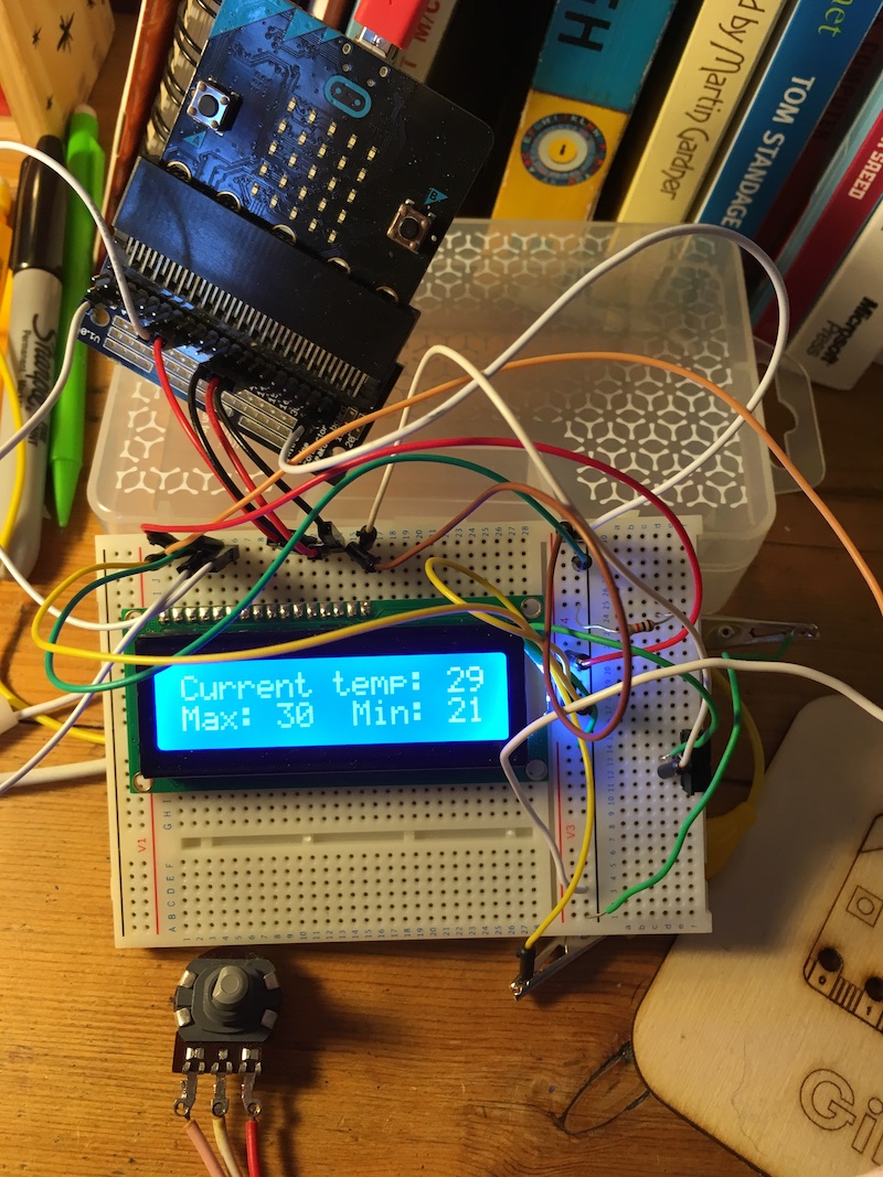
You’ll see in the video that I added a little switch as well to turn the backlight on and off and you’ll see below I found an old volume control or something which I’ve pressed into service as a contrast knob on my maximum / minimum temperature display:
Here’s the Python program that does the temperature display (not including the LCD driver code):
InitDisplay()

def showTemp():
    clear()
    showText('Current temp: ' + str(temperature()) + 'C')
    setCursor(0,1)
    showText('Max: ' + str(maxTemp) + '  Min: ' + str(minTemp))

currentTemp = temperature()
maxTemp = currentTemp
minTemp = currentTemp
showTemp()

while True:
    if currentTemp != temperature():
        currentTemp = temperature()
        if currentTemp > maxTemp:
            maxTemp = currentTemp
        if currentTemp < minTemp:
            minTemp = currentTemp
        showTemp()
    sleep(1000)
It would be nice if someone made an adaptor to allow you to plug one of these common LCD modules straight into a micro:bit, with a USB input for 5v display power, maybe back-powering the micro:bit with 3v?
Now what else shall I do with it? Show received radio messages from other micro:bits, make another Little Box of Poems or other random fact dispenser?
Recommend
About Joyk
Aggregate valuable and interesting links.
Joyk means Joy of geeK