

Teardown: Siemens 8mm SMD Parts Feeder
source link: https://hackaday.com/2020/12/16/teardown-siemens-8mm-smd-parts-feeder/
Go to the source link to view the article. You can view the picture content, updated content and better typesetting reading experience. If the link is broken, please click the button below to view the snapshot at that time.
Teardown: Siemens 8mm SMD Parts Feeder
Many of Hackaday’s readers will be no stranger to surface mount electronic components, to the extent that you’ll likely be quite comfortable building your own surface-mount projects. If you have ever built a very large surface-mount project, or had to do a number of the same board though, you’ll have wished that you had access to a pick-and-place machine. These essential components of an electronics assembly line are CNC robots that pick up components from the reels of tape in which they are supplied, and place them in the appropriate orientation in their allotted places on the PCB. They are an object of desire in the hardware hacker community and over the years we’ve seen quite a few home-made examples. Their workings are easy enough to understand, but there is still much to gain by studying them, thus it was very interesting indeed to see a friend acquiring a quantity of surplus Siemens component feeders from an older industrial pick-and-place machine. A perfect opportunity for a teardown then, to see what makes them tick.
Take Me To Your Feeder
First it’s worth explaining what part a component feeder plays in a pick-and-place machine, and what it does. Components are supplied on flexible tape, sitting in depressions in its surface and covered by a thin plastic cover film that can be peeled back to reveal the part. Using sprocket holes in the edge of the tape, the feeder advances it from one part to the next while peeling back the cover to expose the part. Feeders are usually positioned in a row along the edge of the machine’s work area, such that its head can manoeuvre itself over the part and pick it up before placing it on the board. In the industrial machines this happens very quickly indeed, so the feeders are substantially built to serve many millions of parts over their lifetime.
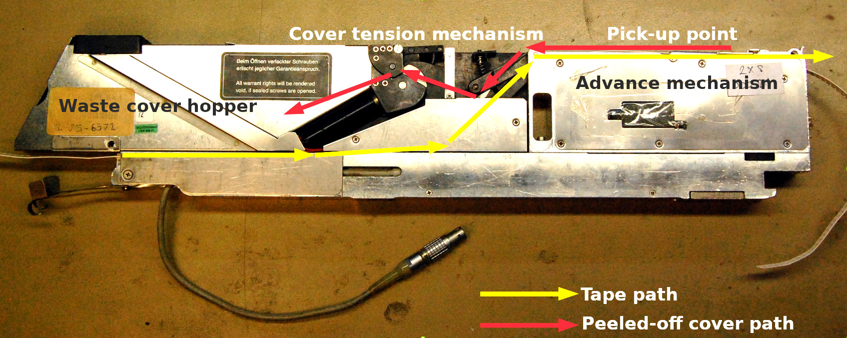
The unit is about 45 mm by 20 mm by 100 mm in size, with a very substantial machined aluminium frame upon which its various components are mounted. It holds not one but two feeders for 8 mm tape, one on either side. Turning it on its side, the front half conceals the feed mechanism with the pick-up point at the top, while at the centre is a tensioning system for the peeled-off cover tape. At the rear is a hopper for spent cover tape, accessible via a spring hatch on the back. On the top at the rear are a pair of membrane buttons, to advance or retard the tape.
The component tape enters underneath at the rear and follows a diagonal path upwards to the top, where it engages with a toothed wheel as part of the feed mechanism. The plastic cover tape is peeled back over itself and fed backwards to the tensioning system in the centre, before disappearing into its hopper. There is a solenoid-controlled shutter over the pick-up point, which is presumably opened by the machine as the pick-up head comes over it. The whole thing is designed for easy removal to be loaded with fresh tapes, so its control cables are brought out to an industrial-grade Neutrik connector.
What’s Inside The Box?
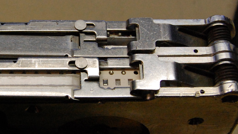
The main mechanisms are easily revealed by releasing the screws holding on their outer panels. In the front is the feed mechanism, which takes the form of a sprocket designed to engage with the holes in the tape. This is driven by a worm drive gear from a motor, which also has an optical encoder to sense how far the tape has been advanced or retarded. Above the motor is a solenoid that operates the shutter, a sliding sheet metal assembly on the top of the unit which exposes the pick-up point.


In the centre of the unit is the cover tape tension mechanism. Another motor and sprocket pulls the cover tape past a spring-tensioned roller, that has an optical sensor to feed back its position. The spent cover tape spools into the hopper at the back, from which it can be emptied upon reel changes. The whole machine is controlled by a microcontroller on a narrow PCB in the base of the unit. The guess is that it’s an older Atmel part, but for now it remains covered by a sticker. Communication with the pick-and-place machine is via a serial connection through that Neutrik connector.


What Can You Do With A Surplus Parts Feeder?
It’s been fascinating to take a look inside this feeder, but what can be done with it? In a literal sense that has an obvious answer of feeding parts to a pick-and-place machine, but the real question is: how can it be used? The interface itself is electrically straightforward, it’s a serial port that uses higher voltage differential signalling to compensate for noisy industrial machinery. The question then remains, how can they be driven, and what are the upgrades?
Happily the availability of these units on the surplus market has meant that hackers have had the chance to work on them. My friend pointed me to both a Gcode driver for them and a replacement PCB design, both on GitHub. Being a relatively easy to understand device, coming up with a way to drive them should be well within the abilities of the type of person who’s prepared to build their own pick and place machine.
A pick and place machine need not be impossible to build, but it’s certain that the component feeders are a significant part of their engineering. Maybe this look at one might shed some light on them, and introduce the option of using a surplus unit rather than attempting to build your own.
Recommend
About Joyk
Aggregate valuable and interesting links.
Joyk means Joy of geeK