

Teardown and exploration of Apple's Magsafe connector
source link: http://www.righto.com/2013/06/teardown-and-exploration-of-magsafe.html
Go to the source link to view the article. You can view the picture content, updated content and better typesetting reading experience. If the link is broken, please click the button below to view the snapshot at that time.
Teardown and exploration of Apple's Magsafe connector
Have you ever wondered what's inside a Mac's Magsafe connector? What controls the light? How does the Mac know what kind of charger it is? This article looks inside the Magsafe connector and answers those questions.
The Magsafe connector (introduced by Apple in 2006) is very convenient. It snaps on magnetically and disconnects if you pull on it. In addition it is symmetrical so you don't need to worry about what side is up. A small LED on the connector changes color to indicate the charging status.
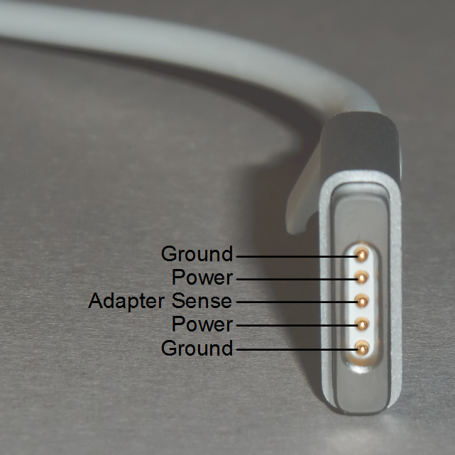
The picture below shows the newer Magsafe 2 connector, which is slimmer. Note how the pins are arranged symmetrically; this allows the connector to be plugged in with either side on top. The charger and computer communicate through the adapter sense pin (also called the charge control pin), which this article will explain in detail below. The two ground pins are slightly longer than the others so they make contact first when you plug in the connector (the same as USB).
Magsafe connector teardown
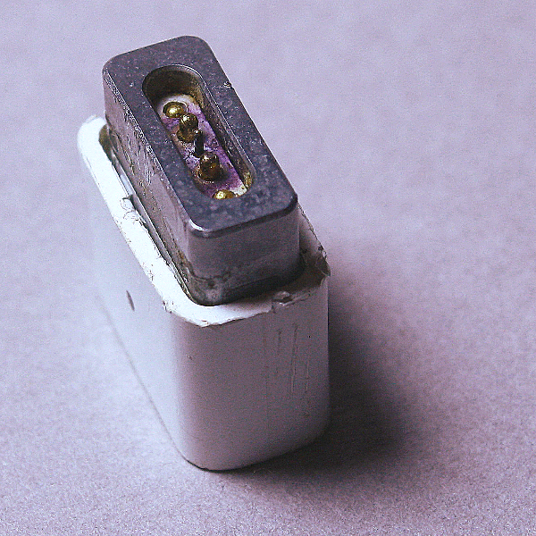
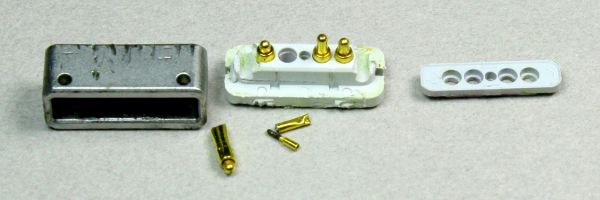
I had a Magsafe cable that malfunctioned, burning the power pins as you can see in the photo below, so I figured I'd tear it down and see what's inside. The connector below is an older Magsafe; notice the slightly different shape compared to the Magsafe 2 above. Also note that the middle adapter sense pin is much smaller than the pins, unlike the Magsafe 2.
Removing the outer plastic shell reveals a block of soft waxy plastic, maybe polyethylene, that helps diffuse the light from the LEDs and protects the circuit underneath.
Cutting through the soft plastic block reveals a circuit board, protected by a thin clear plastic coating. The charger wires are soldered onto the back of this board. Only two wires - power and ground - go to the charger unit. There is no data communication via the adapter sense pin with the charger unit itself.
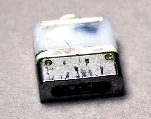
Disassembling the connector shows the spring-loaded "Pogo pins" that form the physical connection to the Mac. The plastic pieces hold the pins in place. The block of metal on the left is not magnetized, but is attracted by the strong magnet in the Mac's connector.
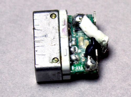
The circuit board inside the Magsafe connector is very small, as you can see below. In the middle are two LEDs, orange/red and green. Two identical LEDs are on the other side. The tiny chip on the left is a DS2413 1-Wire Dual Channel Addressable Switch. This chip has two functions. It switches the status LEDs on and off (that's the "dual channel switch" part). It also provides the ID value to the Mac indicating the charger specifications and serial number.
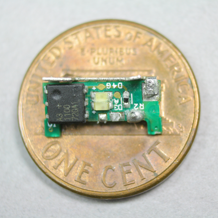
The chip uses the 1-Wire protocol, which is a clever system for connecting low-speed devices through a single wire (plus ground). The 1-Wire system is convenient here since the Mac can communicate with the Magsafe through the single adapter sense pin.
Understanding the charger's ID code
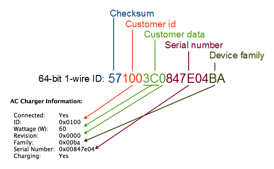
You can easily pull up the charger information on a Mac (Go to "About this Mac", "More Info...", "System Report...", "Power"), but much of the information is puzzling. The wattage and serial number make sense, but what about the ID, Revision, and Family? It turns out that these are part of the 1-Wire protocol used by the chip inside the connector.Every chip in the 1-Wire family has a unique 64-bit ID that is individually laser-programmed into the chip. In the 1-Wire standard, the 64-bit ID consists of an 8-bit family code identifying the type of 1-Wire device, a 48-bit unique serial number, and an 8-bit non-cryptographic CRC checksum that verifies the ID number is correct. Companies (such as Apple) can customize the ID numbers: the top 12 bits of the serial number are used as a customer ID, the next 12 bits are data specified by the customer, and the remaining 24 bits are the serial number.
With this information, the Mac's AC charger information now makes sense and the diagram below shows how the 64-bit ID maps onto the charger information. The ID field 100 is the customer ID indicating Apple. The wattage and revision are in the 12 bits of customer data (hex 3C is 60 decimal, indicating 60 watts). The Family code BA is the 1-Wire family code for the DS2413 chip. Thus, much of the AC charger information presented by the Mac is actually low-level information about the 1-Wire chip.
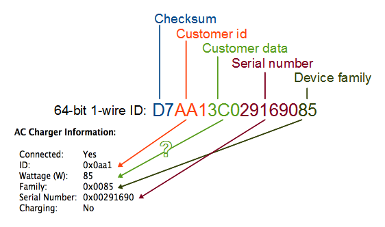
There are a few complications as the diagram below shows. Later chargers use the family code 85 for some reason. This doesn't indicate an 85 watt charger. It also doesn't indicate the family of the 1-Wire device, so it may be an arbitrary number. For Magsafe 2 chargers, the customer ID is 7A1 for a 45 watt charger, 921 for a 60 watt charger, and AA1 for an 85 watt charger. It's strange to use separate customer IDs for the different models. Even stranger, for an 85 watt charger the wattage field in the ID contains 60 (3C hex) not 85, even though 85 watts shows up on the info screen. The Revision is also dropped from the info screen for later chargers.
How to read the ID number
It's very easy to read the ID number from a Magsafe connector using an Arduino board and a single 2K pullup resistor, along with Paul Stoffregen's Arduino 1-Wire library and a simple Arduino program.
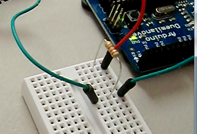
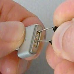
Touching the ground wire to an outer ground pin of the Magsafe connector and the data wire to the inner adapter sense pin will let the Arduino immediately read and display the 64-bit ID number. The charger does not need to be plugged in to the wall - and in fact I recommend not plugging it in - since one interesting feature of the 1-Wire protocol is the device can power itself parasitically off the data wire, without a separate power source.
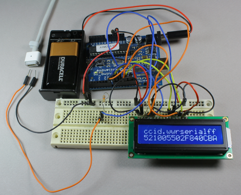
To make things more convenient, the serial number can be displayed on an LCD display. The circuit looks complicated, but it's just a tangle of wires connecting the LCD display. Using a simple program, the 64-bit ID number is displayed on the bottom line of the display. The top line is a legend indicating the components of the code: "cc" CRC check, "id." customer id, "ww" wattage, "r" revision, "serial" serial number, and "ff" family. The number below corresponds to an 85 watt charger (55 hex = 85 decimal).
Controlling the Magsafe status light
The Mac controls the status light in the Magsafe connector by sending commands through the adapter sense pin to the 1-Wire DS2413 switch IC to turn the two pairs of LEDs on or off. By sending the appropriate commands to the IC through the adapter sense pin, an Arduino can control the LEDs as desired.
The picture below demonstrates the setup. The same simple resistor circuit as before is used to communicate with the chip, along with a simple Arduino program that sends commands via the 1-Wire protocol. These commands are described in the DS2413 datasheet but should be obvious from the program code.
I used a cable removed from a dead charger for simplicity. The LEDs are normally powered by the charger's voltage, which I simulated with two 9-volt batteries. To hook the Arduino to the connector, this time I used a Mac DC input board that I got on eBay; this is the board in a Mac that the Magsafe connector plugs into. The only purpose of the board here is to give me a safer way to attach the wires than poking at the pins.
The connector contains a pair of orange/red LEDs and a pair of green LEDs, which can be switched on and off independently. When both pairs are lit, the resulting color is yellow. Thus, the connector can display three colors. The Arduino program cycles through the three colors and off, as you can see from the pictures above.
The charger startup process
When the Magsafe connector is plugged into a Mac, a lot more happens than you might expect. I believe the following steps take place:- The charger provides a very low current (about 100 µA) 6 volt signal on the power pins (3 volts for Magsafe 2).
- When the Magsafe connector is plugged into the Mac, the Mac applies a resistive load (e.g. 39.41KΩ), pulling the power input low to about 1.7 volts.
- The charger detects the power input has been pulled low, but not too low. (A short or a significant load will not enable the charger.) After exactly one second, the charger switches to full voltage (14.85 to 20 volts depending on model and wattage). There's a 16-bit microprocessor inside the charger to control this and other charger functions.
- The Mac detects the full voltage on the power input and reads the charger ID using the 1-Wire protocol.
- If the Mac is happy with the charger ID, it switches the power input to the internal power conversion circuit and starts using the input power. The Mac switches on the appropriate LED on the connector using the 1-Wire protocol.
This process explains why there is a delay of a second after you connect the charger before the light turns on and the computer indicates the battery is charging. It also explains why if you measure the charger output with a voltmeter, you don't find much voltage.
The complex sequence of steps provides more safety than a typical charger. Because the charger is providing extremeley low current at first, there is less risk of shorting something out while attaching the connector. Since the charger waits a full second before powering up, the Magsafe connector is likely to be firmly attached by the time full power is applied. The safety feature are not foolproof, though, as the burnt-up connector I tore apart shows.
Don't try this at home
Warning: I recommend you don't try any of these experiments. 85 watts is enough to do lots of damage: blow out your Mac's DC input board, send flames out of a component, blow fuses, or vaporize PC traces, and that's just the things I've had happen to me. The Mac and charger both have various protection mechanisms, but they won't take care of everything. Poking at your charger while it's plugged in is a high-risk activity.Reading your charger's ID by probing the pins while it's not plugged in is considerably safer, but I can't guarantee it. If you mess up your charger, computer or Arduino you're on your own.
Conclusions
There's more to the Magsafe charger connector than you might expect. The center pin of the connector - the adapter sense pin - controls a tiny chip that both identifies the charger and controls the status LED. It is part of a complex interaction between the charger and the Mac. Using an Arduino microcontroller, this chip can be accessed and controlled using the 1-Wire protocol. Is this useful? Not really, but hopefully you found it interesting.
Recommend
About Joyk
Aggregate valuable and interesting links.
Joyk means Joy of geeK