

Using Quantum Gates instead of Ancilla Bits
source link: https://algassert.com/circuits/2015/06/22/Using-Quantum-Gates-instead-of-Ancilla-Bits.html
Go to the source link to view the article. You can view the picture content, updated content and better typesetting reading experience. If the link is broken, please click the button below to view the snapshot at that time.
Using Quantum Gates instead of Ancilla Bits
22 Jun 2015
This post is the third, and final, part of a worked solution to the following exercise:
In part 1, Constructing Large Controlled Nots, I solved the classical version of the exercise (where an ancilla bit is required).
In part 2, Constructing Large Increment Gates, I did the same thing (one ancilla bit, only classical gates) but for increment operations.
In this part, we're going to use quantum gates (and the constructions from the previous two parts) to avoid that pesky ancilla bit. The basic progression will be as follows:
- Split operations with many controls into sub-operations with fewer controls, by using the fact that quantum operations have square roots.
- Rewrite operations so that controls are only applied to NOT gates.
- Fix smaller and smaller phase shift errors resulting from the above processes.
- Re-arrange the resulting mish-mash of controlled-NOTs into increment and decrement operations.
- Apply the constructions from the previous parts to reduce the remaining large operations into a linear number of Toffoli-or-smaller operations.
(Side note: It's a bit disconcerting to spill nine thousand words on such a short exercise, but I suppose that's the nature of having to explain one level back and noting nearby things instead of just showing the end result.)
Quantum Operations Have Roots
The fundamental property that will allow us to avoid using an ancilla bit, now that we have access to quantum gates, is that every quantum operation has a square root and an inverse. Given a quantum operation U, you can find a quantum operation √U such that applying √U to a circuit twice has the same effect as applying U once. Similarly, applying U and then its inverse U† (or vice versa) will cause the operations to undo each other and result in a net effect of no effect.
Classically, not all operations have square roots. For example, the NOT gate has no classical square root. There's simply no boolean-to-boolean function f such that f(f(x))=¯x. But, quantumly, the NOT gate does have a square root.
Every quantum operation is a unitary matrix, and every unitary matrix is a realizable quantum operation. Unitary matrices always have square roots, and so quantum operations do too. Let's compute a square root of the NOT gate, just to check that this is actually possible. Start with its unitary matrix:
X=[0110]
Then compute the eigenvalues and unit eigenvectors of that matrix:
λ1=1, v1=1√2[11]
λ2=−1, v2=1√2[1−1]
Which gives us the eigendecomposition of the NOT gate's operation:
[0110]=λ1v1v†1+λ2v2v†2=λ112[1111]+λ212[1−1−11]
The eigendecomposition form of a matrix is very useful because most functions, when applied to a matrix, correspond to simply transforming the eigenvalues. To find the square root of the matrix, we simply replace the eigenvalue coefficients with their square roots:
√[0110]=√λ1v1v†1+√λ2v2v†2=√112[1111]+√−112[1−1−11]
And, by arbitrarily picking principal square roots, we find one of the square roots of NOT:
→12[1111]+i12[1−1−11]=12[1+i1−i1−i1+i]
You can check that squaring 12[1+i1−i1−i1+i] does in fact give you [0110]. Engineer a physical instantiation or simulation of 12[1+i1−i1−i1+i], apply it twice, and you will have performed a NOT operation.
The inverse of a unitary matrix is much easier to find than the square root: the inverse is simply the conjugate transpose of the matrix. For example, the inverse of 12[1+i1−i1−i1+i] is just 12[1−i1+i1+i1−i] (another square root of NOT).
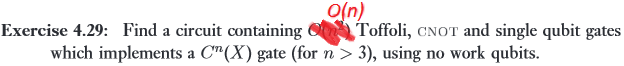
Removing a Control
If you have some operation U with multiple controls, and access to a gate that is the square root of U as well as a gate that is the inverse of that square root, then you can rewrite the circuit to use fewer controls per operation. The construction for doing so is detailed on page 182 of Nielsen and Chuang's textbook. Here it is (note that the top "wire" is actually a bundle of n wires):
Let's convince ourselves, by case analysis, that the above control-reducing construction works. We want there to be no effect if any of the control wires is OFF, but if all of the control wires are ON then the overall effect should be a U applied to the target wire. There are four cases to consider:
- OFF, OFF: If any of the wires in the top wire bundle is OFF, and the middle control wire is also OFF, then none of the operations happen. Clearly this is a no-op overall.
- ON, OFF: If all of the control wires in the top wire bundle are ON, but the middle control wire is OFF, then the middle wire will be temporarily toggled ON during the √U† gate but back OFF for the √U gate that depends on the middle wire. The √U gate that depends on the top control wires does apply, though. Overall nothing happens, because √U†⋅√U=I.
- OFF, ON: If any of the top wire bundle's wires are OFF, but the middle control wire is ON, then basically the same thing happens as in the ON, OFF case. The √U† gate applies, but only one of the √U gates applies, so they undo each other's effects.
- ON, ON: If all of the control wires are ON, then the √U† gate will not occur (because the middle wire was temporarily toggled OFF) but both of the √U gates will fire. So the net effect is a √U2=U operation applied to the target wire.
By case analysis, we see that the control-reducing construction does in fact apply a U if and only if all the controls are ON (and nothing happens otherwise).
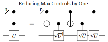
Iteratively Removing Controls Hits a Wall
By nesting the control-reducing construction inside of itself, again and again, we can remove many controls instead of just one:
Unfortunately, this stops working for the last control. The construction will still be correct when there's one control, in that the resulting circuit will be equivalent to the input circuit, but we won't end up with a circuit using no controls:
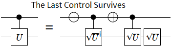
This is a problem, because the surviving controls are on gates that aren't NOT gates, and according to the rules of the exercise we aren't allowed to do that.
We will definitely need to apply the control-reducing construction once, because we need an uninvolved bit in order to apply the constructions from last time and the time before. However, after that single application, we should switch to a construction that moves controls off of special gates and onto NOT gates.
Moving Controls to NOT Gates
It's possible to factor a controlled quantum operation into pieces that only have controls on NOT gates. The overall idea is to find matrices A, B, and C, plus a phase factor eiθ, such that eiθA⋅X⋅B⋅X⋅C=U and A⋅B⋅C=I. Those pieces allow you to do this:
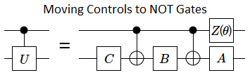
When the control wire in the above circuit is OFF, the overall effect on the bottom wire is A⋅B⋅C. The controlled-NOTs don't fire because their controls are not satisfied, and the phase shift gate (the Z(θ) gate) doesn't fire because phase shifts only apply to the ON state. We required A⋅B⋅C to be equal to the identity matrix, so nothing happened as required. If the control wire was ON, then the overall effect would be eiθA⋅X⋅B⋅X⋅C=U, again as required.
There's a procedure for finding appropriate values for A, B, C, and θ from a given U, but explaining how takes a lot of words. If you're curious, see pages 176, 180, and 181 of the textbook.
For the purposes of this post, we'll only be working with the roots of X gates, and Z gates. I'll just provide some A, B, C, and θ values that work.
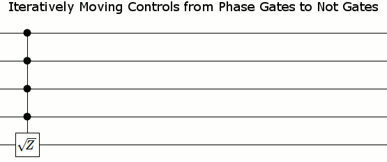
For phase shift gates, i.e. Z-axis rotations, moving controls onto NOT gates is relatively simple. You phase shift each of the two wires by half as much, phase shift in the opposite direction (also by half as much) when the wires differ, and that's all:
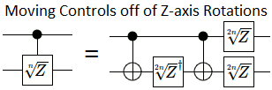
(Note that, by n√Z, I always mean [100eiπ/n]. I don't mean an arbitrary n'th root of Z.)
To turn the Z-axis rotation construction into an X-axis rotation construction, we use the fact that bracketing with Hadamard gates transforms Z rotations into X rotations, and vice versa:
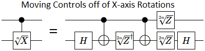
It's easiest to apply the Hadamard bracketing one time at the very top level before we've even applied the control-reducing construction, instead of doing it as part of each transformation we make to the circuit.
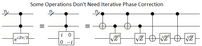
Iterative Phase Corrections
The control-moving constructions from the previous part have a problem: the top wire ends up with an operation, instead of just controls. When there are multiple control wires present, that new operation on the top wire (which is not a NOT) becomes a controlled operation:
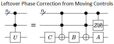
Fortunately, because the new controlled operation has one fewer control than the original controlled operation, fixing the problem is just a matter of repeating the procedure again and again. Eventually the resulting phase correction will have no controls. Here is what the repeated application looks like:
And here are the start and end states without animation in between:
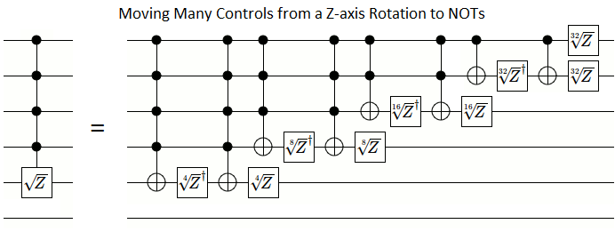
So far, we've managed to reduce the maximum number of controls, and to move all of the controls to NOT gates. But we still need to clean up a bit.
Re-arranging into Increments
The construction so far creates a linear number of NOT gates. However, because those NOT gates have many controls, individually breaking them down into Toffoli gates would create a quadratic number of gates overall. Instead, we will re-arrange the NOT gates so that we can simplify the circuit.
Because neither phase shift gates nor controls affect whether a wire is ON, we can move controlled-NOT gates over phase shift gates as long as the phase shift applies to one of the control wires (as opposed to the target wire). We can also move controlled-NOTs over other controlled-NOTs under the same conditions, as long as the other controlled-NOT cancels its effects by happening twice.
This freedom of movement is all we need to re-arrange our controlled-NOTs into an increment gate and a decrement gate:
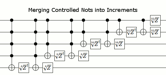
Here's where we were before moving controls, where we ended up after moving controls, and the final compact circuit after simplifying:
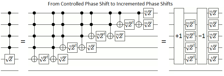
The final state ends up being surprisingly simple... but why does it work? Let's try to understand how controls can be replaced by incrementing.
Think of each phase shift gate as adding or subtracting some value from a global counter, but the gate only fires and adjusts the count when the wire the phase shift gate is on is ON. If the smallest phase shift gate adds a into the global counter, then here is the overall pattern of gates:
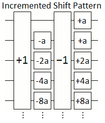
(Note that the "+1" and "-1" gates are working on the 2's complement value stored in the wires, not the global counter. Sorry if that's confusing.)
There are two important details to notice. First, except for the top-most wire, the phase shift gates on each individual wire are opposites. Second, each phase shift gate inside the increment and decrement gates subtracts an amount equal to the sum of the amounts added by the phase shift gates that are higher-up and outside the increment and decrement gates.
Suppose the k'th wire is OFF, and all the wires for lesser bits are ON. Then every wire up to and including the k'th wire will get toggled by the increment gates. Furthermore, the inside gate on the k'th wire will fire while the outside gates on the lower bit wires will fire. But the inside gate of the k'th wire subtracts the same amount that all of the outside gates on the lesser wires add. Therefore the phase shift gates on the wires up to and including the first OFF bit have no net effect.
Suppose the k'th wire is OFF, but some lower bit wire is also OFF. Then the increment's carry propagation will stop before reaching the k'th wire, and it will not be toggled. Therefore the the phase shift gates on the k'th wire will either both fire, undoing each other, or neither will fire. So the phase shift gates on wires after the first OFF bit have no net effect.
Together, the previous two paragraphs show that if there is any OFF bit, nothing happens. Phase shift gates on each wire after the first OFF wire will undo themselves, and the phase shift gate on that first OFF wire will undo the phase shift gates on previous wires.
That just leaves the case where all the bits are ON. Incrementing the all-ON state gives the all-OFF state. Therefore none of the inside gates will fire, but all of the outside gates will fire. The sum of the outside gates is a+a+2a+4a+...+2n−1a where n is the number of involved wires, meaning the net effect is to add 2na to the global counter.
So, by setting a to 12n'th of the phase shift we want, the incremented phase shift circuit will add that phase shift into the global counter if and only if all of the wires are ON. Exactly what we wanted.
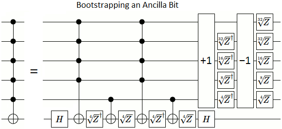
Putting it All Together
Our construction so far is as follows:
- Replace the controlled-X that depends on every wire with a controlled-Z, by bracketing it with Hadmard gates.
- Free up a borrowable ancilla bit by using the control-reducing construction.
- Repeatedly apply the control-removing construction, until only NOT gates have controls on them.
- Re-arrange the resulting controlled-NOTs into increments.
Here are the starting and ending states, for 6 wires. Notice that all of the operations on the right hand side leave at least one wire unaffected, so that the classical constructions from the previous parts will be applicable:
Let's convince ourselves that this overall construction works.
We already know that the increment-decrement part acts like a controlled-√Z; it will add a phase factor of i to the ON, ON, ON, ON, ON, ON and ON, ON, ON, ON, ON, OFF states.
We also know that the surrounding Hadamard gates just switch between Z-rotation and X-rotation, so if we pretend the Hadamards aren't there and find that the circuit implements a controlled-Z then the circuit works.
All that's left to account for is the four 4√Z/4√Z† and controlled-NOT gates at the start.
Well, when all the control wires are ON, and the target wire is OFF, both of the √Z† gates will fire and the ON, ON, ON, ON, ON, OFF state will gain a phase factor of −i.
And when all the wires are ON, both of the √Z gates fire instead and the ON, ON, ON, ON, ON, ON state will gain a phase factor of +i.
The overall effect on the ON, ON, ON, ON, ON, OFF state was to gain a phase factor of i and a phase factor of −i.
In other words, there was no overall effect, because i⋅−i=1.
That leaves ON, ON, ON, ON, ON, ON as the only affected state, and it gained two phase factors of i for a net phase shift of i2=−1.
Therefore the circuit, when ignoring the Hadamard gates, is a controlled-Z operation that depends on every wire.
Meaning the overall circuit is in fact a full controlled-X, as desired.
That's it. Reduce the large controlled-nots and increments into a linear number of Toffoli-or-smaller gates by using the constructions from the last two posts, and we're done. I would show the resulting circuit in a diagram, if it weren't for the fact that the construction uses something like ≈100n gates. Clearly, in practice, it's more efficient to just have n zeroed ancilla bits available for use (because then you'd only need ≈2n gates).
That being said... isn't it bad that our solution needs smaller and smaller gates as n increases?
Trying to Avoid Exponentially Precise Gates
Needing smaller and smaller gates is bad because, in practice, you only have a finite gate set and a finite amount of precision. For example, the most common quantum error correction scheme stops at the 4√Z gate.
Is there any way to avoid needing more and more precise gates? Well, there are a few possible workarounds:
Approximate: If you have a gate, or sequence of gates, that rotates by an irrational fraction of a turn, then you can get arbitrarily close to any given angle by repeating that rotation many times. For example, if you are given a gate that phase shifts by π degrees (not radians, degrees), then applying that gate 6634751 times will get you within 0.000003 degrees of a 45 degree phase shift.
Don't Bother: If you simply don't perform the phase corrections, something happens. In the case of an un-phase-corrected controlled-Z, what happens is you apply the operation eiZπ/2 instead. If that happens to be the operation you wanted to apply, then mission accomplished!
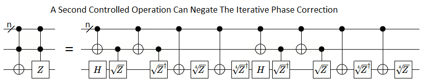
Cancel it Out: If you happen to be applying two full-controlled operations, you can arrange for the phase corrections from one to exactly cancel out the phase corrections from the other:
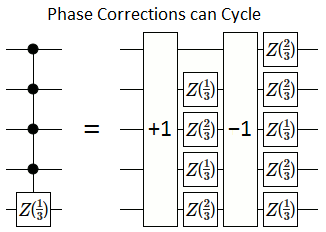
Use an Uneven Root: If your controlled operation is a p'th root of the identity matrix, and p is not even, then the phase corrections will cycle. For example, Z2/3 is a cubic root of the identity matrix. It is also its own fourth root, so the phase corrections can bounce between Z2/3 and Z4/3 instead of becoming exponentially small:
Have an Ancilla Bit: With an ancilla bit, the classical construction from part 1 works (without using any square roots). In practice, this is how you would solve the problem.
Unfortunately, none of the above workarounds apply to the exercise we're solving, and I suspect that there's simply no way to avoid the exponentially precise gates without cheating.
Unavoidable Exponentially Precise Gates
The reason I suspect that the exponentially precise gates are necessary has to do with thinking of phases as counters.
Suppose that we are given a very precise phase shift gate: 2p√Z for some large p. Applying 2p√Z a total of 2p+1 times will rotate any affected phases by a full turn, back to where they started. In effect, this means we can treat each state as having a counter that wraps around after being incremented 2p+1 times.
Let's consider what happens to the counter system when we apply our available operation, and compare that to what happens when we apply our desired operation.
When we apply the 2p√Z gate, any states where the target wire is ON will have their counters incremented. This adds 2n−1 increments into the counter system, because that's how many states there are where the target wire is ON.
Applying the desired operation, a controlled-Z that depends on every wire, only affects the all-ON state. However, the counter is incremented 2p times (adding 2p increments into the counter system), instead of once, because that's how many increments it takes to go half-way around.
A counter wrapping around, from 2p+1 to 0, removes 2p+1 increments from the system. The operation we can perform adds 2n−1 increments into the system. The operation we want to perform must add exactly 2p increments into the system.
Oh my.
Unless 2p is a multiple of lcm(2n−1,2p+1), it is impossible for us to add exactly 2p increments into the counter system by applying our available operation (even if we're allowed to repeatedly permute the states and apply the operation). Unless min(p+1,n−1)≤p, we're screwed. As soon as n exceeds p+1, we won't be able to simulate a fully-controlled-Z operation anymore for the same reason that you can't reach an odd total by adding up only even numbers.
(Why doesn't this argument also apply to the case where there's an ancilla bit? Because then the target operation adds 2p into two states, for a total change of 2p+1, and that's always a multiple of lcm(2p+1,2n−1).)
This is not proof positive that we need exponentially precise gates to solve the exercise. In particular, there may be some clever way of partially rotating around the X or Y axies in addition to the partial rotations around the Z axis. However, I would find that pleasantly surprising because it seems to be hard to get back to a nice fraction of a turn after combining rotations around two axies (not counting 90 degree rotations or undoing each rotation in reverse order, of course).
Feel free to surprise me.
Summary
Unlike classical computers, quantum computers don't need an ancilla bit to perform a controlled-NOT that depends on every wire. They have the option of using exponentially precise phase shift gates instead.
In either case a linear number of Toffoli-or-smaller gates is needed but, pragmatically speaking, it's simpler and more efficient to just have an ancilla bit available.
Navigation
Part 1: Constructing Large Controlled-Nots
Part 2: Constructing Large Increment Gates
Part 3: (This Post)
Recommend
About Joyk
Aggregate valuable and interesting links.
Joyk means Joy of geeK