

Perspective! 2: the actual practicalities of drawing shit in perspective
source link: https://canmom.github.io/animation/perspective-practical
Go to the source link to view the article. You can view the picture content, updated content and better typesetting reading experience. If the link is broken, please click the button below to view the snapshot at that time.
Perspective! 2: the actual practicalities of drawing shit in perspective
home animationSo far we've seen:
- perspective is a set of conventions for representing depth, which nowadays mostly serves to evoke photography
- the perspective construction is based on a point called the 'centre of projection', and a specific image surface (a flat one, in rectilinear perspective)
- every point in a perspective drawing represents a distinct direction, travelling away from this centre of projection until it hits something, like a laser beam coming out of your eye
- if we look at a perspective drawing from anywhere other than the 'centre of projection', which is almost always the case, it may look distorted
- if we don't want these distortions for artistic effect, we should limit our field of view
There are two ways to go about making a perspective drawing. The first way is to be really meticulous and do everything very carefully with vanishing points. The second way is to just wing it: it will be ‘wrong’ but nobody will notice. However, it helps to practice the ‘right’ way to build the intuition that lets you do it the ‘fast’ way without anyone catching you without getting out a ruler.
Most of the time, when you do a meticulously accurate perspective drawing, what you’re gonna be drawing is a cuboid. Or at the very least, a flat, rectangular surface. If you’re drawing something else, you’ll probably start by projecting a rectangular grid, and then using that grid to help you draw the angular or curvy shape you actually wanted to draw.
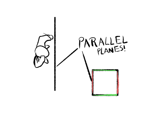
So why do we like flat rectangular surfaces so much? This all comes back to the fundamental most important fact about perspective: if a collection of lines is parallel in world space, they all point towards the same, specific point in canvas space. This point is called the ‘vanishing point’ for that direction. We like rectangles because they have parallel sides, which we can point towards the same vanishing point.
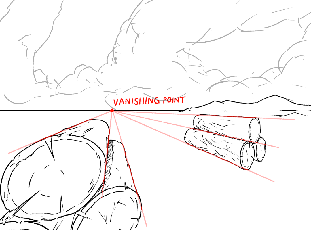
You know earlier when we said that each point on the image corresponds to the direction of a laser beam coming out of your eye? Well, any line that points in the same direction as that laser beam in world space will point towards its corresponding point in screen space. For example, imagine some logs are laid out like this:
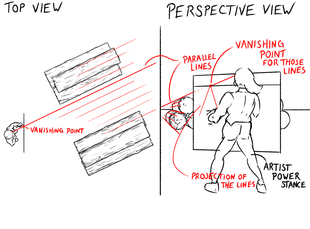
Shoot your eye laser out parallel to the logs. This will hit your canvas at a certain point; that’s your vanishing point. When you draw the logs, since they’re all parallel to that laser beam in world space, they all converge towards its vanishing point in canvas space:
From this key perspective fact, basically all else follows!
We have one other technicality to clear up. As your eye lasers shoot out and hit the perspective plane, somewhere (possibly outside the actual canvas!) they will be hitting it ‘dead on’, perpendicular to the image plane.
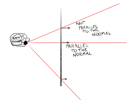
This ‘dead on’ direction is often singled out in perspective drawing, and sometimes referred to as the view direction - however I think that's a potentially confusing name, so instead I'm going to call it the normal direction. ('Normal' in this context means 'perpendicular to a plane'.) Its vanishing point in canvas space is called the principal point. There’s nothing intrinsically special about this direction compared to the others, but it can be useful to keep track of it once we start messing around with planes. And, as we saw in the previous article, if you want to minimise perspective 'distortion', you should make sure the principal point is near the centre of your picture.
“How many” vanishing points
Perspective lessons often break things down into ‘one point’, ‘two point’ or ‘three point’ perspective. Though this scheme makes drawing simpler, it is, to me, not a very helpful way to introduce it.
Instead, I’d say there is one set of directions which are special: the ones which are parallel to the image plane. Imagine you shoot your eye laser exactly along the surface of your canvas. It will never hit it, even if you run it backwards out the back of your head as well. There is no vanishing point - or, equivalently, the vanishing point is equally far away.
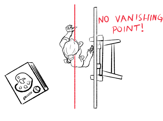
This means that if something is flat and parallel with the image plane, it has the same shape in canvas space as it does in world space!
Usually, we assume the surface we’re perspective projecting onto is vertical. If that’s the case, then vertical lines in 3D space are also going to be vertical - they won’t converge to a point.
Now, suppose we want to draw a cube. A cube has three sets of edges, each of which will have a different vanishing point.
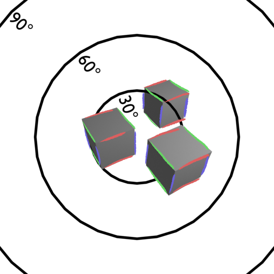
If we’re looking at it ‘end on’, by which I mean, looking at it so the nearest face is parallel to the image plane, that face will simply look like a square. We can see that in the render from earlier:
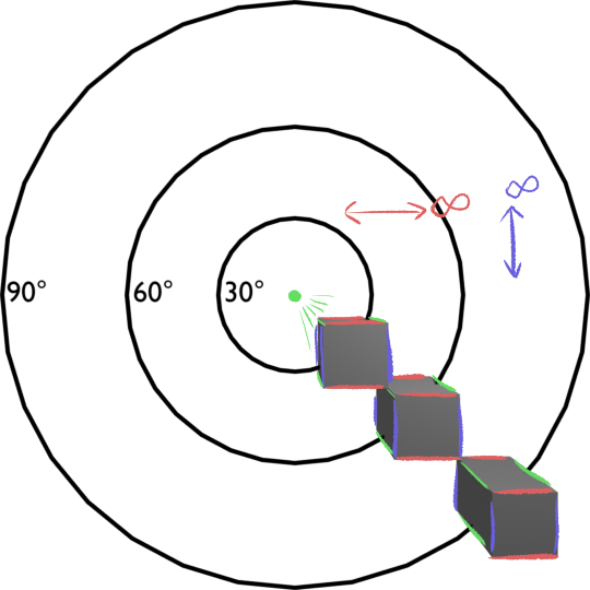
All three cubes have the same, equally sized square end; only the sides which aren’t parallel to the image plane look different when we move the cubes around!
Let's look at each set of parallel edges:
- The red and blue edges have infinitely distant vanishing points.
- The green edges are parallel to the normal direction, so they all converge to its vanishing point, the so-called 'principal point'. We cropped the picture so the principal point is in the middle, so they all converge towards the middle.
This setup is known as ‘one point’ perspective, since these cubes have exactly one vanishing point. Of course, if there were some cubes in the scene rotated to a different angle, this would not be true!
Most of the time we won’t meet the cubes ‘end on’. The main use for ‘one point’ perspective is when we’re looking down a long corridor or street. In this case, it’s pretty common to put the image plane perpendicular to the direction of the street.
OK, now let’s turn the cube around a bit. The vertical edges (blue) are still parallel to the image plane. But the other edges are not parallel to the image plane, so they’ll get vanishing points.
First, here it is from above:
And now, ‘two point’ perspective:
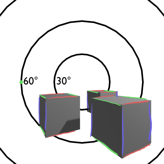
Here, the vanishing point for the red lines falls outside the 75-degree FOV of the image. The vanishing point for the green lines is inside the image. (Remember, these circles are marked with FOVs, not the angle from the central ray.)
Two point perspective is commonly used to show architecture in backgrounds.
Finally, ‘three point’ perspective shows cuboids where none of the faces are parallel to the image plane. Realistically, the vast majority of cuboids are in this condition. In this case, all three sets of lines have a vanishing point. Typically, your ‘camera’ is angled downwards:
The bad news is that a great deal of the time in a realistic composition, your cubes will be in this perspective. The good news is that it’s pretty easy to just wing it for at least a few of those vanishing points once you figure out how it works; you almost never have to actually construct three distinct vanishing points.
How far apart to place your vanishing points
When I first started trying to teach myself perspective drawing, the question of how far apart to place my vanishing points (in canvas space) was quite a headache. Nobody seemed to give the answer, beyond a vague admonition not to put them too close together.
This question is a matter of judgement, but hopefully what we’ve just seen can help us understand what we're actually deciding. Vanishing points represent directions; if we have a cuboid shape then its vanishing points are 90 degrees apart.
This means:
- if our vanishing points are close together, we have a wide-angle picture, like a wide-angle lens on a camera. perspective distortions will be very extreme.
- if our vanishing points are far apart, we have a narrow-angle picture, like a zoom lens. perspective distortions will be mild.
- if our vanishing points are infinitely far apart, we have an 'orthgraphic' rather than 'perspective' drawing, mostly used in diagrams. there are no perspective distortions at all.
However, it’s not so simple as ‘x distance on the paper = y degrees of view angle’. That would be true if we were drawing on the surface of a sphere, but we’re drawing on a flat piece of paper! Near to the ‘principal point', we’re looking at the paper straight on. When we look far away from that point, we’re glancing the paper at an oblique angle.
This means that angles are arranged in canvas space in an uneven way, like this:
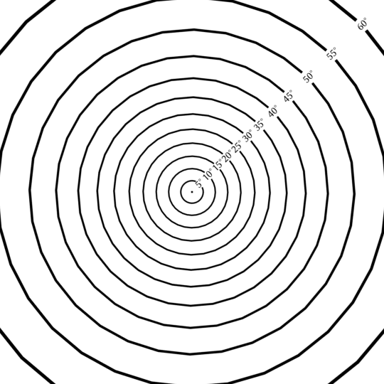
(If you want to draw one of these yourself, the radius of a circle representing an angle θ from the normal direction is proportional to tanθ.)
These angle circles can be used to measure the angles between eye lasers going through two different points, as long as the points are in a line with the principal point. Which is, admittedly, a pretty big limitation, but the circles help us get a sense of the layout of canvas space.
So if there’s 90 degrees separating two vanishing points, we could put them both on opposite sides of the 45° radius circle (since 45°+45°=90°). In this case, we’d get a perspective drawing like this:

In this case, the vanishing points are 384 pixels apart. But suppose we rotated this around the vertical axis by 15 degrees. This moves one vanishing point onto the 30°-radius circle (since 45∘−15∘=30∘), and the other on the 60°-radius circle (since 45∘+15∘=60∘).

There is one other wrinkle. If you’re doing a full, three-point perspective, how do you make sure your third vanishing point is consistent with the lens angle implied by the other two? This is something it's usually fairly easy to get away with just guessing, but we'll return to this question in the next post when we talk about planes and vanishing lines.
Winging it
Have a look at all those cubes we’ve rendered just now. Let’s notice some Rectangle Facts™:
- the faces of a cube, and rectangles in general, are always convex quadrilaterals (a needlessly fancy way to say ‘four-sided shapes’) in perspective, because straight lines in world space are also straight lines in canvas space
- these quadrilaterals taper off towards the vanishing points. opposite pairs of edges share a vanishing point.
- the more the rectangle is rotated perpendicular to the image plane in world space, the thinner it looks in canvas space. this is called foreshortening and we'll discuss it more later!
Fortunately for us, just about any convex quadrilateral could be a perspective projection of some rectangle. In fact, it could be the projection of a whole set of different rectangles, depending where the point of projection is sitting! Moreover, we humans are generally not great at figuring out whether it’s the right rectangle, as long as it’s near enough. In fact, the wrong projection might even look nicer sometimes.
Here are some convex quadrilaterals:
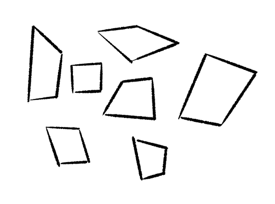
Any of these could a rectangle, projected in perspective. But which one do you pick for the rectangle you want to draw?
Let’s assume you’re starting with a square. Here’s how you figure out what it ought to look like:
- if we’re looking straight at it (i.e. near parallel to the image plane), all the sides are gonna be roughly the same length.
- if we’re glancing by it at an angle, it will look thinner, and it will taper (get narrower from one side to the other)
- how much does it taper? that basically depends how near the camera it is. if it’s a long way away, it will be very thin and not taper very much. if it’s nearby, it will be thicker, but also taper a lot.
In this animation, these three identical squares are spaced equally along a line in world space, and rotating at the same speed:
The one on the left is much nearer, and so it tapers a lot more when it turns.
Why should this be? It has to do with the way perspective usually compresses distances along the normal direction much more for faraway objects than nearby objects.
It does what now?
Distance in perspective
Suppose you’re drawing a railway line. In world space, the railway sleepers are instantly far apart. But let’s have a look at what happens to them in perspective.
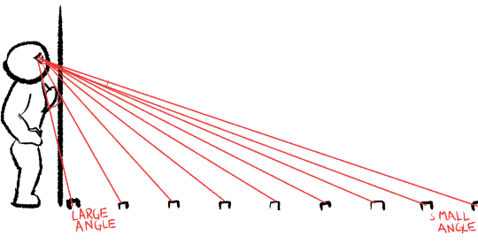
There are two effects here which are going to affect things. Firstly, let’s look at your eye lasers. Remember, perspective drawings represent the directions towards things. So since your eye lasers are wider apart for nearby things, the gaps between the nearby sleepers will appear to be bigger. We know this from everyday experience: far away things look small.
But there’s a second effect that compounds this. Notice that, for the nearby things, our eye lasers are hitting the canvas at a really oblique angle. This means the drawings of the two railways sleepers need to be even further apart in canvas space!
This is the reason why we try to keep the ‘principal point’, i.e. the point where our eye lasers are perpendicular to the image plane, near to the centre of the image, and limit the overall field of view. The viewer will probably not be sitting at the exact centre of projection, so these measures help avoid the distortions from looking too weird.
It also explains a general rough principle to keep in mind: stuff that’s near to you will look more ‘perspectivey’ than stuff that’s far away. Another way of looking at it: when stuff is nearby, the ‘near’ side will look much bigger than the far side of an object. When stuff is far away, the near and far sides will appear similar sizes, so it will look much closer to an ‘orthographic’ (non-perspective) projection.
This implies: if something is equally spaced in world space, it gets increasingly clustered in canvas space the further away it is.
Suppose you’re looking at a long street: the nearby buildings will take up lots of space in the frame. The faraway buildings will be reduced to slivers!
Now, how does this relate to our rotating squares? Consider a rotating object. As it rotates, one side gets nearer, the other gets further away. If the object is near the camera (point of projection), this leads to a much bigger change of shape in perspective space than if it’s a long way away.
Soon, we'll look at some more specific perspective tricks: how to build up relationships between the shapes we draw in perspective, to make sure your lines and planes are at the 'right' size and 'right' angles in relation to each other. But first, we have to meet planes and their vanishing lines.
Recommend
About Joyk
Aggregate valuable and interesting links.
Joyk means Joy of geeK