

Measuring keyboard-to-photon latency with a light sensor
source link: https://thume.ca/2020/05/20/making-a-latency-tester/
Go to the source link to view the article. You can view the picture content, updated content and better typesetting reading experience. If the link is broken, please click the button below to view the snapshot at that time.

For a long time when I’ve wanted to test the latency of computers and UIs I’ve used the Is It Snappy app with my iPhone’s high speed camera to count frames between when I press a key and when the screen changes. However the problem with that is it takes a while to find the exact frames you want, which is annoying when doing a bunch of testing. It also makes it difficult to find out what the variability of latency is like. I had already made this kind of testing easier by adding a mode to my keyboard firmware which changes the LED color after it sends a USB event , but that only made it a bit faster and more precise. I wanted something better.
So I followed in the footsteps of my friend Raph and made a hardware latency tester which sends keyboard events and then uses a light sensor to measure the time it takes for the screen to change! It was quite easy and in this post I’ll go over some of the latency results I’ve found, talk about why good latency testing is tricky, and explain how to build your own latency tester.
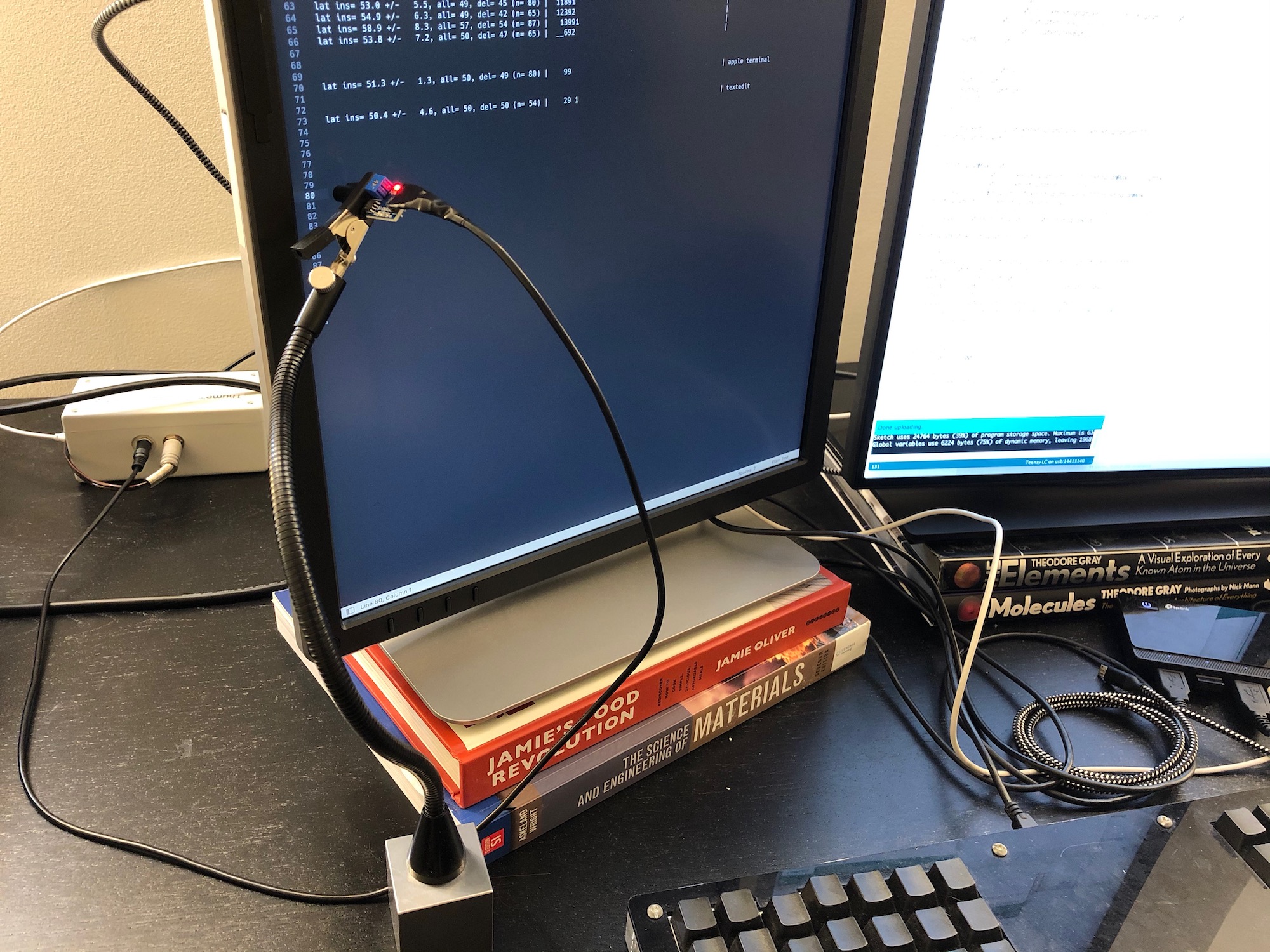
Basically my latency tester is a light sensor module from Amazon held by an adjustable holder arm wired to a Teensy LC microcontroller which presses “a” and waits until the light level changes, then deletes it and keeps collecting samples as long as a button is held. Then with a short press of that one button it will type out a nice latency histogram that looks like this:
lat i= 60.3 +/- 9.3, a= 60, d= 59 (n= 65,q= 41) | 239_ |
This line tells me the average latency of insertions ( i=
), deletions ( d=
) and both put together ( a=
), the standard deviation of insertion times ( +/-
), measurement count ( n=
) and quality ( q=
), and a little ascii histogram where each character is a 10ms bucket and the digits proportionally represent how full the bucket is. The _
represents a bucket with at least one sample but not enough to be at least one ninth of the top bucket, so I can see tail latencies. Here’s what it looks like (pictured with portrait monitors but all tests were done in landscape):
I also made it so if you press the button again, it will type out all the raw measurements like [35, 35, 33, 44]
so you can do custom plotting:
Monitor latency
I’ll start out with my favorite set of results:
Sublime Text, macOS, distraction-free full-screen mode on two 4k monitors:
lat i= 35.3 +/-   4.7, a= 36, d= 36 (n= 67,q= 99) |  193       | Dell P2415Q top
lat i= 52.9 +/-   5.0, a= 53, d= 54 (n= 66,q= 45) |   _391     | Dell P2415Q bottom
lat i= 65.1 +/-   5.0, a= 64, d= 63 (n=109,q=111) |    _292    | HP Z27 top
lat i= 79.7 +/-   5.0, a= 80, d= 80 (n= 98,q=114) |       89_  | HP Z27 bottom
There’s a lot to observe here:
- First of all, I like how the single-line fixed-width histogram format lets me put results next to each other in a text file and label them to the right for comparison.
- We can see the expected difference of 16ms between the latency at the top and bottom of each monitor from the time it takes to scan out the rows during a frame at 60hz.
- The standard deviation is just a touch over the 4.6ms that’s inherent to the uniformly-distributed variance that comes from being misaligned with a 16ms display refresh period.
- The HP Z27 is around 30ms slower than the Dell P2415Q! And that’s measuring from the start of when the change is detectable, I’m pretty sure the Z27 also takes longer to transition fully. With the Z27 and Sublime almost half my end-to-end latency is unnecessary delay from the monitor!
All measurements in the rest of this post are accordingly done on my Dell P2415Q. Both monitors have response time set to “fast”, the Z27 has even higher response time settings but they only affect transition time and introduce unsightly ghost trails without helping initial latency.
The perils of measurement
Taking good latency measurements is actually quite difficult in more ways than you might think. I tried harder than most people to get realistic measurements and still failed the first few times in ways that I had to fix.
Actually measuring end to end latency
First of all, the reason to use a hardware latency tester is that there are many incomplete or potentially deceptive ways to measure end-to-end latency.
There’s a really excellent famous blog post called Typing With Pleasure that compares latency of different text editors on different operating systems with good analysis and pretty graphs. However it does this by simulating input events and screen scraping using OS APIs. I haven’t done any overlapping measurements with his so can’t point to anything specifically wrong, but there’s lots of potential issues with this. For example inspecting the screen buffer on the CPU might unduly penalize GPU-rendered apps due to window buffer copies under some ways that capture might work. Simulated input may hit different paths than real input. Regardless, even if it does give decent relative measurements (and you can’t truly know without validating it against an end-to-end test), it doesn’t tell you the full latency users experience.
Using 1000hz USB polling
One source of latency users experience that my tester doesn’t measure is keyboard latency . Many keyboards can introduce more latency than my entire keyboard-to-photon latency ( including mine in the past ) due to 8ms USB polling intervals, low keyboard grid scan rates, slow firmware, and more debatably different mechanical design.
You can’t just use any microcontroller that can emulate a keyboard to build a low-variance latency tester because they probably use default 125Hz polling. Luckily my go-to microcontroller the Teensy LC is one of few to default to 1000hz.
Ensuring good signal strength
For the first while after I built my latency tester I didn’t have any measurement of signal strength. Eventually I got confused by some measurements in slightly different scenarios with the same app and screen having wildly different results. I did some testing and figured out that sometimes with small fonts or poor sensor placement the change in screen contents would only barely be detectable so I’d end up measuring until the monitor finished transitioning when usually I measure until when the monitor starts transitioning (which is its own tricky subjective measurement choice).
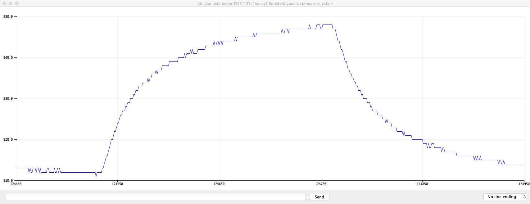
I knew to suspect transition time, because before I wrote the firmware I played around with just sampling the light sensor every millisecond and using the Arduino serial plotter to plot measurements as I typed and backspaced a letter just to see what the signal looked like. You can see that some combination of the light sensor and the monitor take nearly 100ms to fully transition. Based on filming with Is It Snappy it seems like it only takes my Z27 about 20ms for the screen to perceptually finish transitioning.
To avoid this I added a peak to peak signal strength measurement after the full transition to my output so I could ensure I was getting adequate resolution for my threshold of 5 steps to be near the beginning of the transition. These are the numbers you see after q=
. I learned that it’s important to keep font sizes large and screen brightness settings high.
Significant variation from small differences
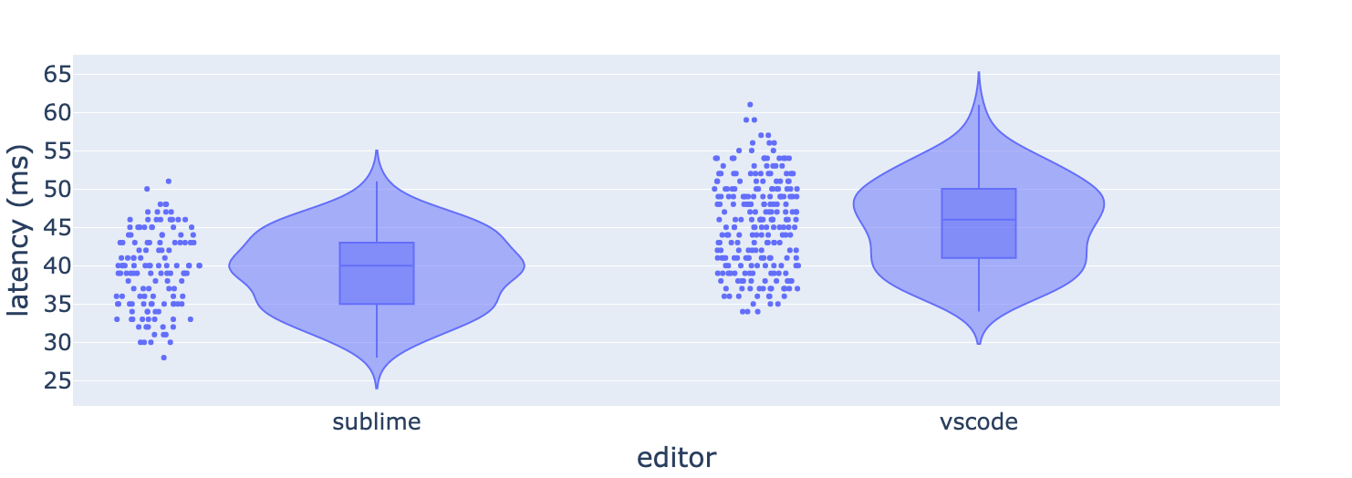
It’s possible for seemingly small differences in what’s being measured to make noticeable differences in latency. For example I wanted to see if there was a significant difference between the latency of Sublime and VSCode on a small file with plain text highlighting compared to a large file with a complex highlighting grammar and an autocomplete popup. Sure enough there was, but after noticing some variability I did a bunch more testing and discovered that the latencies were noticeably different between typing ‘a’ on a blank line and typing ‘a’ after an existing ‘a’ (‘aa’).
Here’s the results upon making a new line after line 3469 of 6199 of the huge parser.rs , all taken with similar sensor positioning lower down my Dell monitor than the very top.
lat i= 40.2 +/-   4.1, a= 40, d= 39 (n= 38,q= 90) |  _89           | sublime small .txt

lat i= 41.2 +/-   6.9, a= 41, d= 42 (n= 54,q= 92) |   992          | sublime aa parser.rs
lat i= 43.6 +/-   6.1, a= 43, d= 42 (n= 48,q=100) |   492          |
lat i= 52.2 +/-   6.0, a= 52, d= 52 (n= 26,q=100) |    49          |
lat i= 44.3 +/-   5.6, a= 43, d= 42 (n= 45,q=100) |   391          |
lat i= 42.7 +/-   7.6, a= 42, d= 42 (n= 46,q=100) |  _491          |

lat i= 48.1 +/-   6.8, a= 49, d= 50 (n= 43,q= 89) |   269          | sublime a parser.rs
lat i= 43.9 +/-   5.4, a= 48, d= 52 (n= 32,q= 97) |   197          |
lat i= 47.8 +/-   8.4, a= 49, d= 49 (n= 29,q= 97) |   197_         |
lat i= 46.1 +/-   6.8, a= 47, d= 49 (n= 42,q= 97) |   196_         |

lat i= 63.3 +/-   9.3, a= 63, d= 62 (n= 68,q=118) |    _963__      | vscode aa parser.rs
lat i= 63.6 +/-   7.6, a= 64, d= 65 (n= 71,q=139) |    _49__     _ |
lat i= 62.3 +/-   6.3, a= 61, d= 59 (n= 52,q=132) |    _791        |
lat i= 62.0 +/-   5.8, a= 61, d= 60 (n= 40,q=111) |    _49_        |
lat i= 61.9 +/-   9.7, a= 62, d= 61 (n= 35,q=111) |     981_       |

lat i= 53.1 +/-   7.7, a= 51, d= 49 (n= 54,q=116) |   _79__        | vscode a parser.rs
lat i= 52.2 +/-   6.3, a= 52, d= 51 (n= 41,q=133) |    692         |
lat i= 53.2 +/-   7.8, a= 52, d= 52 (n= 57,q=134) |    591_        |
lat i= 52.1 +/-   7.1, a= 52, d= 52 (n= 55,q=134) |    591_        |
I did a bunch of runs at different times and with minor changes to confirm the effect, and you can see that there’s variation between measurements of the same scenario, but noticeably larger variation between just typing ‘a’ and adding an ‘a’ after an existing ‘a’. Try looking at the ‘a=’ column since it includes both insert and delete measurements so has the least cross-run noise. Sublime is faster at ‘aa’ than ‘a’ and VSCode is faster at ‘a’ than ‘aa’.
In both editors ‘aa’ causes the autocomplete popup to alternate between two lists and ‘a’ causes it to appear and disappear. I can guess that Sublime might be slower in the ‘a’ case because opening and closing the autocomplete popup has a cost, but I don’t have a strong hypothesis why VSCode is slower in the ‘aa’ case on both insertion and deletion.
Jittering so as not to sync with refresh
The next fishy thing I noticed is that my variances seemed too low. I was sometimes getting standard deviations of 1ms when my understanding of how the system worked said I should be getting a standard deviation over 4.6ms due to 16ms screen refresh intervals.
I looked at my code and figured out that I was inadvertently synchronizing my measurement with screen refreshes. Whenever I measured a change, my firmware would wait exactly 300ms before typing ‘a’ or backspace again and taking another measurement. This meant the input was always sent about 300ms after a screen refresh and thus would land at a fairly constant spot in the screen refresh interval. I patched this issue by adding a 50ms random delay between measurements.
This mainly leads to incorrectly low variances but might lead to incorrect averages as well if the app will miss a paint deadline if the input event comes late in a frame but it never does during the test. I found this during testing for this post and couldn’t be bothered to redo all the tests below this point, so you may notice some low variances, but I did recheck the averages on important results like Sublime and VSCode.
Text editors
I tested the latency of a bunch of text editors on the same plain text file, but note the above that these are before I added jittering, although I did more tests on Sublime and VSCode after jittering which you can see above.
lat i= 32.5 +/-   4.0, a= 34, d= 35 (n= 38,q= 78) |   9_          | sublime text
lat i= 33.4 +/-   1.4, a= 33, d= 33 (n= 68,q= 23) |  _9           | textedit
lat i= 47.6 +/-   7.0, a= 47, d= 47 (n= 71,q=130) |   219         | vscode
lat i= 34.2 +/-   3.5, a= 34, d= 33 (n= 57,q= 37) |   9 _         | chrome html input
lat i= 33.2 +/-   1.1, a= 33, d= 33 (n= 55,q= 30) |   9           | stock mac emacs
lat i= 45.6 +/-   7.0, a= 43, d= 41 (n= 35,q= 56) |   992_        | atom
lat i= 35.0 +/-   4.7, a= 35, d= 35 (n= 66,q= 11) |   9__         | xi
Given the lack of jitter, I’d interpret these results as everything except VSCode and Atom being similarly “basically as good as you can get”. And note that even VSCode and Atom have less of a latency penalty for normal typing than you can easily have in your monitor or keyboard.
Terminals
I also measured different terminals. It looks like the default Apple Terminal and kitty have similar approximately optimal latency, while iTerm2 and Alacritty have worse latency.
lat i= 53.1 +/-   6.6, a= 54, d= 55 (n= 53,q= 59) |    291      _ | iterm2 gpu render
lat i= 50.5 +/-   2.5, a= 50, d= 50 (n= 56,q= 59) |    19_        | iterm2 no gpu
lat i= 35.8 +/-   7.0, a= 34, d= 33 (n= 73,q= 48) |   9___        | apple terminal
lat i= 35.1 +/-   2.5, a= 34, d= 32 (n= 35,q= 52) |   9_          | apple terminal vim
lat i= 50.4 +/-   3.9, a= 50, d= 49 (n= 60,q=269) |   _59         | alacritty
lat i= 36.1 +/-   5.6, a= 35, d= 34 (n= 78,q=199) |   9__         | kitty
How to make one
Here’s the parts list I used:
- $12 : A Teensy LC or any other Teensy 3+. You could also use an Arduino, but the Teensy’s USB library uses 1000hz polling (1ms latency) while most USB devices default to 125hz (an extra 8ms of random latency in your measurements). It’s possible you may be able to get your microcontroller of choice to do 1000hz polling though. If you don’t want to have to solder the pins, buy one with pre-soldered pins, this might require getting the more expensive Teensy 3 if you want Amazon Prime shipping.
- $12 : A light sensor module (Amazon only has 10 packs, I only used 1). You could make your own circuit for this but these modules save a lot of time and are easy to integrate.
- $13 : A helping hand to hold the light sensor up to your screen in a stable position.
- A button/switch of some kind to trigger testing
- Wires to connect the light sensor, Teensy, and button
- Electrical tape to make a black soft shield to restrict the view of the sensor
- A USB micro-B cable to connect the Teensy to your computer
There’s an awful lot of flexibility in exactly how you assemble it. You just need to somehow connect 3 wires (3V, ground, analog out) from the light sensor module to the corresponding pins on the Teensy (3V, ground and any analog-capable pin). The easiest way to do this which doesn’t even require any soldering if you buy a Teensy with pre-soldered header pins is to use 3 female to female jumper wires . Then you just need some kind of switch to activate the latency test where you wire one pin to ground on the Teensy and another pin to a digital IO pin. This can be as simple as two wires that you touch together if you’re really lazy!
To make sure the light sensor module only sees a limited area of the screen I wrapped the sensor in a little cylinder of electrical tape and snipped off the end cleanly with scissors. This made a little round window I could press up against the screen with the helping hand to minimize outside interference and get the cleanest signal.
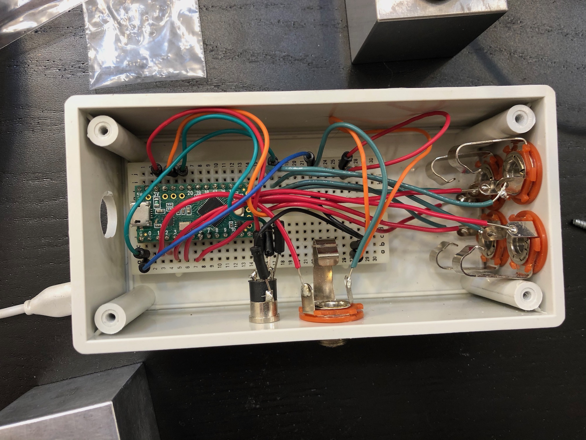
I had already made a foot pedal box with a Teensy LC and a little breadboard inside, and it had an extra TRRS jack on the side I had put on anticipating this sort of project, so for me the project was soldering the light sensor module to a TRRS cable. Then I could just use one of my existing foot pedals to control the testing!
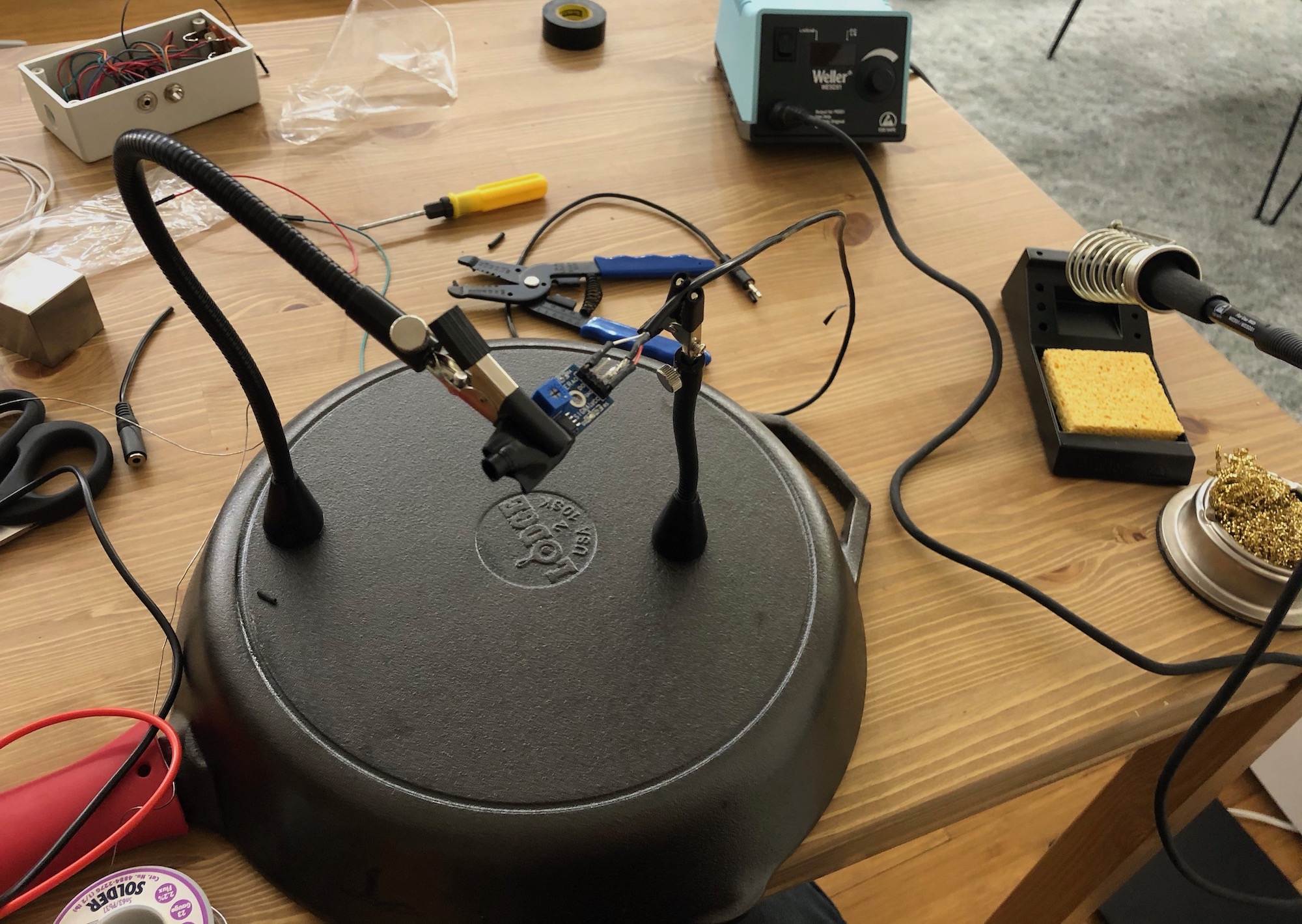
For the soldering I was in luck since I had conveniently bought magnetic helping hands for the project which I could use for the soldering process. Inconveniently I realized that I actually didn’t own many substantial chunks of iron for them to attach to, so I ended up using a cast iron pan when soldering andmy tungsten cube when on my desk (which turns out to be slightly ferromagnetic).
I encourage you to have fun and try to make something fancier than just dangling jumper wires. For my foot pedal box I bought a plastic project box from a local electronics shop, used a drill press to put some holes in the sides and installed large and small headphone jacks and a little breadboard so I could reconfigure how things connect. There’s tons of foot pedals on Amazon for tattoo machines and electric pianos that use 1/4” phone plugs that you can pick and choose from. These are my favorites for feel and silence but there are cheaper options that can be unreliable, hard to press or loud.
I wouldn’t recommend following my use of a TRRS jack for the sensor module though, they’re nice and small and there’s lots of cables available, but I used them before I realized the problem that they cause a lot of shorting of different connections when plugging and unplugging. I tried to minimize this by putting power and ground on opposite ends, but you should consider some better cable type like maybe a phone cable .
The firmware
I didn’t write the fanciest possible firmware to find the beginning and ending of the transition, but I put a bit of effort into tweaking it to work well and adding various features so I recommend starting with my firmware. Install the Teensyduino software and then you can use my latency tester Arduino sketch which also doubles as foot pedal box code but you can comment that stuff out and configure it to use the right pins. Then just long press your switch to take samples and short press to type out the results!
Recommend
About Joyk
Aggregate valuable and interesting links.
Joyk means Joy of geeK