

Runtime Mesh Manipulation With Unity [FREE]
source link: https://www.tuicool.com/articles/hit/AVvqyyn
Go to the source link to view the article. You can view the picture content, updated content and better typesetting reading experience. If the link is broken, please click the button below to view the snapshot at that time.
Welcome to the world of 3D objects and mesh manipulation! One of the benefits of using Unity as your game development platform is its powerful 3D Engine. Along with its ability to use custom editors , it makes the development of 3D games and apps so much easier.
With the growth of virtual reality and augmented reality (VR/AR) technology, most developers will inadvertently find themselves wrestling with the gritty bits of 3D concepts. So let this tutorial be your starting point. Don’t worry, there will be no complicated 3D math here — just lots of hearts, drawings, arrows and loads of fun!
Note: This tutorial is intended for users who are familiar with Unity’s integrated development environment (IDE) and have some experience with C# programming. Otherwise, do check out Introduction to Unity UI and Introduction to Unity Scripting first.
You need to have at least Unity 2017.3.1 installed. If not, please download the latest version of Unity here . This tutorial utilises a custom editor, you can find out more about it at Extending the Unity Editor .
Getting Started
First, familiarize yourself with these basic 3D technical terms to help you better understand this tutorial.

Basic 3D Technical Terms:
- Vertices : Each vertex is a point in 3D space.
- Mesh : Holds all the vertices, edges, triangles, normals and UV data of the model.
- Mesh Filter : Stores the mesh data of the model.
- Mesh Renderer : Renders the mesh data in the scene.
- Normals : The directional vector of a vertex or a surface. This characteristically points outward, perpendicular to the mesh surface.
- Lines/Edges : The invisible lines that connect vertices to one another.
- Triangles : Formed when three vertices are connected by edges.
- UV Map : Maps a material to an object to give it texture and color.
The anatomy of a 3D object starts with its mesh. The construction of this mesh starts with its vertices. The invisible lines that connect these vertices form triangles, which define the basic shape of the object.

Normals and UV data then provide shading, color and texture. This mesh data is stored in the mesh filter, and the mesh renderer uses this data to draw the object in the scene.
Hence, to create a 3D model in pseudocode:
- Create a new mesh named “myMesh”.
- Add data to myMesh’s vertices and triangle properties.
- Create a new mesh filter named “myMeshFilter”.
- Assign myMesh to myMeshFilter’s mesh property.
Now that you have the basics covered, download the project using the Download Materials button at the top or bottom of this page, unpack the files and open the starter project in Unity. Check out the folder structure in the Project window :
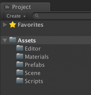
Folders explained:
- Prefabs : This contains a Sphere prefab, to be used for saving your 3D mesh at runtime.
- Scenes : This contains three scenes, which will be used in this tutorial.
- Editor : The Scripts inside this folder give you special powers in the editor during development.
- Scripts : This includes runtime scripts which, when attached to a GameObject, execute when you click Play .
- Materials : This folder contains the Material for the mesh.
In the next section, you will create a custom editor to visualize the constructs of a 3D mesh.
Poking and Prodding Meshes With a Custom Editor
Open 01 Mesh Study Demo inside the Scenes folder. In the Scene view , you will see a 3D cube:

Before diving into the mesh, let’s look at a custom editor script.
Customizing Editor Script
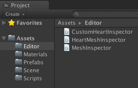
Select the Editor folder in the Project window . Scripts in this folder add functionality to the Editor during development and are not available in Build mode.
Open up MeshInspector.cs
and view the source code. All Editor script needs to implement the Editor
class, its attribute CustomEditor
tells the Editor
class which object type it’s an editor for. The OnSceneGUI()
is an event method that lets you draw stuff in the Scene view; OnInspectorGUI()
lets you customise the Inspector with extra GUI elements.
In MeshInspector.cs
, before the start of the MeshInspector
class, add the following:
[CustomEditor(typeof(MeshStudy))]
Code explained:
Here, the CustomEditor
attribute tells Unity which object type the custom editor class can edit.
In OnSceneGUI()
, before EditMesh()
, add the following:
mesh = target as MeshStudy;
Debug.Log("Custom editor is running");
Code explained:
The Editor
class has a default target
variable. Here, the target
is cast to MeshStudy
. Now, the custom editor will draw any GameObject with MeshStudy.cs
attached to it in the Scene view. Adding a debug log allows you to see in the console that the custom editor is indeed running.
Save the file and return to Unity. Go to the Scripts folder and drag MeshStudy.cs onto the Cube GameObject in the Hierarchy to attach it.

The console should be logging the message “Custom editor is running” now, which means the setup was successful! Feel free to remove the debug log at this time so that it doesn’t flood your console.
Cloning and Reseting Mesh
In handling a 3D mesh with a custom editor in Edit mode, be careful not to overwrite Unity’s default mesh. If that happens, you will need to restart Unity.

To safely clone the mesh without overwriting its original form, make a copy of the mesh from the MeshFilter.sharedmesh
property and assign it back to the mesh filter.
To do this, double-click on MeshStudy.cs
in the Scripts
folder to open the file with your favorite code editing software. This script inherits from the MonoBehaviour
class and its Start()
function will not run in Edit mode.
In MeshStudy.cs
, before the start of the MeshStudy
class, add in the following:
[ExecuteInEditMode]
Code explained:
By adding this attribute, the Start()
function will now fire in both Play mode and Edit mode. Now you can instantiate and clone your mesh object first.
In InitMesh()
add the following code:
oMeshFilter = GetComponent<MeshFilter>();
oMesh = oMeshFilter.sharedMesh; //1

cMesh = new Mesh(); //2
cMesh.name = "clone";
cMesh.vertices = oMesh.vertices;
cMesh.triangles = oMesh.triangles;
cMesh.normals = oMesh.normals;
cMesh.uv = oMesh.uv;
oMeshFilter.mesh = cMesh;  //3

vertices = cMesh.vertices; //4
triangles = cMesh.triangles;
isCloned = true;
Debug.Log("Init & Cloned");
Code explained:
-
Grabs original mesh
oMeshfrom theMeshFiltercomponent. -
Copies to a new mesh instance
cMesh. - Assigns the copied mesh back to the mesh filter.
- Updates local variables.
Save
the file and return to Unity. The debug console should show the message “Init & Cloned.” Select the Cube
GameObject in the Hierarchy
and check its properties in the Inspector
. The Mesh Filter
should show a mesh asset named clone
. Great! This means you have cloned the mesh successfully.

Under the Editor folder, go to MeshInspector.cs
. In OnInspectorGUI()
, after the second line of code, add the following:
if (GUILayout.Button("Reset")) //1
{
    mesh.Reset(); //2
}
Code explained:
- This code draws a Reset button in the Inspector .
-
When pressed, it calls the
Reset()function in MeshStudy.cs .
Save
the file, open MeshStudy.cs
, and add the following into the Reset()
function:
if (cMesh != null && oMesh != null) //1
{
    cMesh.vertices = oMesh.vertices; //2
    cMesh.triangles = oMesh.triangles;
    cMesh.normals = oMesh.normals;
    cMesh.uv = oMesh.uv;
    oMeshFilter.mesh = cMesh; //3

    vertices = cMesh.vertices; //4
    triangles = cMesh.triangles;
}
Code explained:
- Checks that both original and clone mesh exists.
-
Resets
cMeshto the original mesh. -
Assigns
cMeshback tooMeshFilter. - Updates local variables.
Save the file and return to Unity. In the Inspector , click on the Test Edit button to mess with the cube’s mesh. Next, press the Reset button; the cube should return to its original form.

Understanding Vertices and Triangles With Unity
A mesh consists of vertices connected by edges to form triangles. Triangles define the basic shape of the object.
The Mesh Class:
Vector3
So in a simple Quad mesh that consists of four vertices and two triangles, its mesh data would be as follows:

Presenting Vertices
Here, you want to present the vertices on the cube with blue colored dots.
In MeshInspector.cs
, look for the EditMesh()
function and add the following:
handleTransform = mesh.transform; //1
handleRotation = Tools.pivotRotation == PivotRotation.Local ? handleTransform.rotation : Quaternion.identity; //2
for (int i = 0; i < mesh.vertices.Length; i++) //3
{
    ShowPoint(i);
}
Code explained:
-
The
handleTransformgets Transform values frommesh. -
The
handleRotationgets the current pivot Rotation mode. -
Loops through the mesh vertices and draws dots with
ShowPoint().
In the ShowPoint()
function, right after the //draw dot
comment, add:
Vector3 point = handleTransform.TransformPoint(mesh.vertices[index]);
Code explained:
This line converts the vertex local position into world space.
Within the same function, in the if statement
block, right after the previously added line of code, add the following:
Handles.color = Color.blue;
point = Handles.FreeMoveHandle(point, handleRotation, mesh.handleSize, Vector3.zero, Handles.DotHandleCap);
Code explained:
Handles
Handles.FreeMoveHandle()
Save the file and return to Unity. Check out the cube's property in the Inspector and be sure that the Move Vertex Point option is on. You should now see the mesh marked with some blue dots on screen. There you go ~ the vertices of the cube mesh! Try it with other 3D objects and see the results.

Moving a Single Vertex
Start with the most basic step of mesh manipulation by moving a single vertex first.
Go to MeshInspector.cs
. Inside the ShowPoint()
function, right after the //drag
comment, just before the closing braces in the if statement
block, add the following:
if (GUI.changed) //1
{
    mesh.DoAction(index, handleTransform.InverseTransformPoint(point)); //2
}
Code explained:
-
GUI.changedmonitors any changes made to the dots, which works nicely withHandles.FreeMoveHandle()to detect a dragging action. -
On drag vertex, the
mesh.DoAction()function will receive its index and Transform values as params. Since the vertex Transform values are in world space, you convert it to local space withInverseTransformPoint().
Save
the script file and go to MeshStudy.cs
. In DoAction()
, after the opening braces add the following:
PullOneVertex(index, localPos);
Then add the following to the PullOneVertex()
function:
vertices[index] = newPos; //1
cMesh.vertices = vertices; //2
cMesh.RecalculateNormals(); //3
Code explained:
newPos
cMesh.vertices
RecalculateNormals()
Save the file and return to Unity. Try dragging one of the dots on the cube; did you see a broken mesh?
It seems like some of the vertices share the same position, so when you pull only one, the other vertices stay behind, and your mesh breaks. In the next section, you will fix that problem. :]
Finding All Similar Vertices
Visually, a cube mesh is made up of eight vertices, six sides and 12 triangles. Let's see if that is true.

Go to MeshStudy.cs
, before the Start()
function, and look for a variable named vertices
. You will see this:
[HideInInspector]
public Vector3[] vertices;
Code explained:
[HideInInspector]
hides a public variable from the Inspector window
.
Now comment out that attribute:
//[HideInInspector]
public Vector3[] vertices;
Note:
Hiding the vertices value with [HideInInspector]
helps with more complicated 3D meshes. As the array size of vertices can go into the thousands, this will cause Unity to freeze up if you try to view the array value in the Inspector.
Save
the file and return to Unity. Go to the Inspector
. You can now see the vertices
property under the Mesh Study
script component. Click on the arrow icon beside it; it should expand to an array of Vector3
elements.
You can see that the array size is 24, which means that there are vertices sharing the same position! Remember to uncomment [HideInInspector]
before you proceed.
[spoiler title = "Why 24 Vertices?"]
There are many theories to this. But the simplest answer is that:
A cube has six sides, and each side is made up of four vertices to form a plane.
So, the calculation: 6 x 4 = 24 vertices.
Feel free to explore the other answers. For now, just know that certain meshes will have vertices sharing the same position.

[/spoiler]
In MeshStudy.cs
, replace all
the code inside the DoAction()
function with:
PullSimilarVertices(index, localPos);
Go to the PullSimilarVertices()
function and add the following:
Vector3 targetVertexPos = vertices[index]; //1
List<int> relatedVertices = FindRelatedVertices(targetVertexPos, false); //2
foreach (int i in relatedVertices) //3
{
    vertices[i] = newPos;
}
cMesh.vertices = vertices; //4
cMesh.RecalculateNormals();
Code explained:
-
Gets the target vertex position, to be used as an argument to the
FindRelatedVertices()method. - This method returns a list of indices (that correspond to vertices) that share the same position as the target vertex.
-
Loops through that list and update the related vertices with
newPos. -
Assigns the updated
verticesback tocMesh.vertices. ThenRecalculateNormals()to re-draw the mesh with the new values.
Save the file and return to Unity. Click and drag any of the vertices; the mesh should now retain its form without breaking.

Now that you have covered the first step in mesh manipulation, save the scene and move on to the next segment.
Manipulating Meshes
In this segment, you will learn about manipulating meshes in real time. While there are many ways to do that, this tutorial will feature the most basic form of mesh manipulation, which is simply the pushing and pulling of predefined vertices of the mesh.

No math...
Collecting the Selected Indices
Start by selecting the vertices to be displaced in real time.
Open up the 02 Create Heart Mesh scene inside the Scenes folder. You will see a red colored sphere in the Scene view. Select the Sphere in the Hierarchy and go to the Inspector . You will see the Heart Mesh script component attached.
Now, you want an Editor script for this object to display the mesh vertices in the Scene view. Go to the Editor folder and double-click on HeartMeshInspector.cs .
In the ShowHandle()
function, inside the if statement
block, add the following:
Handles.color = Color.blue;
if (Handles.Button(point, handleRotation, mesh.pickSize, mesh.pickSize, Handles.DotHandleCap)) //1
{
    mesh.selectedIndices.Add(index); //2
}
Code explained:
Handles.Button
mesh.selectedIndices
In OnInspectorGUI()
, before the closing braces, add the following:
if (GUILayout.Button("Clear Selected Vertices"))
{
    mesh.ClearAllData();
}
Code explained:
This adds a custom Reset button in the Inspector
to invoke mesh.ClearAllData()
.
Save
the file and open up HeartMesh.cs
from the Scripts
folder. In the ClearAllData()
function, add the following:
selectedIndices = new List<int>();
targetIndex = 0;
targetVertex = Vector3.zero;
Code explained:
This clears the values in selectedIndices
and targetIndex
. It also resets targetVertex
to zero.
Save the file and return to Unity. Select the Sphere and go to the HeartMesh script component in the Inspector . Expand Selected Indices by clicking on the arrow icon beside it. This helps you monitor every vertex that you add into the list.
Toggle on Is Edit Mode with the Checkbox icon beside it. This will draw the mesh's vertices in the Scene view. When you click on the blue dots, the values should be updated in Selected Indices accordingly. Also test the Clear Selected Vertices button to make sure it clears all values correctly.
Note: You have the option to show/hide the transform handle with Show Transform Handle in the custom Inspector . Just remember not to panic when you find the Transform handle missing from your other scenes! Be sure to switch it back on before you exit.
Deforming the Sphere Into a Heart Shape
Updating mesh vertices in real time basically involves three steps:
mVertices
mVertices
mVertices
Go to HeartMesh.cs
, and before the Start()
function, declare the following variables:
public float radiusofeffect = 0.3f; //1
public float pullvalue = 0.3f; //2
public float duration = 1.2f; //3
int currentIndex = 0; //4
bool isAnimate = false;
float starttime = 0f;
float runtime = 0f;
Code explained:
selectedIndices
In the Init()
function, before the if statement
block, add:
currentIndex = 0;
Code explained:
When the player starts, currentIndex
is set to 0 — the first index of the selectedIndices
list.
Still in the Init()
function, before the closing braces of the else statement
block, add:
StartDisplacement();
Code explained:
Run the StartDisplacement()
function if isEditMode
is false.
Inside the StartDisplacement()
function, add the following:
targetVertex = oVertices[selectedIndices[currentIndex]]; //1
starttime = Time.time; //2
isAnimate = true;
Code explained:
targetVertex
isAnimate
After the StartDisplacement()
function, create the FixedUpdate()
function with the following:
void FixedUpdate() //1
{
    if (!isAnimate) //2
    {
        return;
    }

    runtime = Time.time - starttime; //3

    if (runtime < duration)  //4
    {
        Vector3 targetVertexPos = oFilter.transform.InverseTransformPoint(targetVertex);
        DisplaceVertices(targetVertexPos, pullvalue, radiusofeffect);
    }
    else //5
    {
        currentIndex++;
        if (currentIndex < selectedIndices.Count) //6
        {
            StartDisplacement();
        }
        else //7
        {
            oMesh = GetComponent<MeshFilter>().mesh;
            isAnimate = false;
            isMeshReady = true;
        }
    }
}
Code explained:
-
The
FixedUpdate()function runs on a fixed FPS loop. -
If
isAnimateis false, skip the code below. -
Updates the
runtimeof the animation. -
If
runtimeis within thedurationlimit, get the world space coordinates oftargetVertexandDisplaceVertices()surrounding the target vertex with thepullvalueandradiusofeffectas params. -
Otherwise, time is up. Add one to
currentIndex. -
Checks if
currentIndexis within the number ofselectedIndices. Move on to the next vertex in the list withStartDisplacement(). -
Otherwise, at the end of the list, update
oMeshdata with the current mesh and setisAnimateto false to stop the animation.
In DisplaceVertices()
, add the following:
Vector3 currentVertexPos = Vector3.zero;
float sqrRadius = radius * radius; //1

for (int i = 0; i < mVertices.Length; i++) //2
{
    currentVertexPos = mVertices[i];
    float sqrMagnitute = (currentVertexPos - targetVertexPos).sqrMagnitude; //3
    if (sqrMagnitute > sqrRadius)
    {
        continue; //4
    }
    float distance = Mathf.Sqrt(sqrMagnitute); //5
    float falloff = GaussFalloff(distance, radius);
    Vector3 translate = (currentVertexPos * force) * falloff; //6
    translate.z = 0f;
    Quaternion rotation = Quaternion.Euler(translate);
    Matrix4x4 m = Matrix4x4.TRS(translate, rotation, Vector3.one);
    mVertices[i] = m.MultiplyPoint3x4(currentVertexPos);
}
oMesh.vertices = mVertices; //7
oMesh.RecalculateNormals();
Code explained:
- The square of the radius.
- Loops through each vertex in the mesh.
-
Gets
sqrMagnitudebetweencurrentVertexPosandtargetVertexPos. -
If
sqrMagnitudeexceedssqrRadius, continue to the next vertex. -
Otherwise, proceed on to determine the
falloffvalue, based on the current vertexdistancefrom the center point of area of effect. -
Sums up the new
Vector3position and applies its Transform to the current vertex. -
On exiting the loop, assign the updated
mVerticestooMeshdata, and have Unity adjust the normals.
Original Source of the Falloff Technique
The original formula is from the Procedural Examples asset package file, downloadable for free from the Unity Asset Store.
Save your file and return to Unity. Select the Sphere , go to the HeartMesh component, and try adding some vertices into your Selected Indices property. Turn off Is Edit mode and press Play to preview your work.
Play around with the Radiusofeffect , Pullvalue and Duration settings to see different results. When you are ready, update the settings per the screenshot below.

Press Play . Did your sphere balloon into a heart shape?
Congratulations! In the next section, you will save the mesh into a prefab for further use.

Saving Your Mesh in Real Time
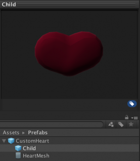
To save the procedural heart-shaped mesh in Play mode, you need to prepare a prefab that has a 3D object as its child, then replace its mesh asset with a new one via a script.
In the Project view, find the CustomHeart in the Prefabs folder. Click on the Arrow icon to expand its contents and select Child . You will see a Sphere object in the Inspector preview screen. This is the prefab that will hold the new mesh data.

Open up HeartMeshInspector.cs
. Inside OnInspectorGUI()
function, before the closing braces, add the following:
if (!mesh.isEditMode && mesh.isMeshReady)
{
    string path = "Assets/Prefabs/CustomHeart.prefab"; //1

    if (GUILayout.Button("Save Mesh"))
    {
        mesh.isMeshReady = false;
        Object pfObj = AssetDatabase.LoadAssetAtPath(path, typeof(GameObject)); //2
        Object pfRef = AssetDatabase.LoadAssetAtPath (path, typeof(GameObject));
        GameObject gameObj = (GameObject)PrefabUtility.InstantiatePrefab(pfObj);
        Mesh pfMesh = (Mesh)AssetDatabase.LoadAssetAtPath(path, typeof(Mesh)); //3
        if (!pfMesh)
        {
            pfMesh = new Mesh();
        }
        else
        {
            pfMesh.Clear();
        }
        pfMesh = mesh.SaveMesh(); //4
        AssetDatabase.AddObjectToAsset(pfMesh, path);

        gameObj.GetComponentInChildren<MeshFilter>().mesh = pfMesh; //5
        PrefabUtility.ReplacePrefab(gameObj, pfRef, ReplacePrefabOptions.Default); //6
        Object.DestroyImmediate(gameObj); //7
    }
}
Code explained:
-
Sets
pathto the CustomHeart prefab object. -
Creates two objects from the CustomHeart
prefab, one to be instantiated as a GameObject (
pfObj), the other one as a reference (pfRef). -
Creates an instance of the mesh asset
pfMeshfrom CustomHeart . If not found, create a new mesh, otherwise clear existing data. -
Updates
pfMeshwith new mesh data, and adds it as an asset to CustomHeart . -
Updates the mesh asset in
gameObjwithpfMesh. -
Replaces CustomHeart
with
gameObjby matching pre-existing connections. -
Destroys
gameObjimmediately.
Save
your file and go to HeartMesh.cs
. In the public method SaveMesh()
, after nMesh
instantiates, add in the following:
nMesh.name = "HeartMesh";
nMesh.vertices = oMesh.vertices;
nMesh.triangles = oMesh.triangles;
nMesh.normals = oMesh.normals;
Code explained:
Returns a mesh asset with values from the heart-shaped mesh.
Save the file and return to Unity. Press Play . When the animation ends, a Save Mesh button will appear in the Inspector . Click on the button to save your new mesh, then stop the player.
Go to the Prefabs folder and check out the CustomHeart prefab. You should now see a spanking new heart-shaped mesh sitting nicely in your CustomHeart prefab object.

Good Job!
Putting It All Together
In the previous scene, the DisplaceVertices()
function uses the Falloff formula to determine the pull strength to be applied to each vertex within the defined radius. The 'fall off' point — where the pull strength starts decaying — depends on the type of Falloff used: Linear, Gaussian or Needle. Each type produces different results on the mesh.


Like cupcake toppings...
In this section, you will look at another option to manipulate vertices with the use of a pre-fixed curve. Based on the principle that velocity equals distance divided by time (d=(v/t)), you can determine the vector's position by referencing its distance divided by its time factor.
Using the Curve Method
Save your current scene and open up 03 Customize Heart Mesh from the Scenes folder. You will see an instance of the CustomHeart prefab in the Hierarchy . Click on the Arrow icon beside it to expand its contents and select Child .
View its properties in the Inspector . You will see the Mesh Filter component with the Heart Mesh asset. Attach the Custom Heart script to Child as a component. The asset should now change from HeartMesh to clone .
Next, open up CustomHeart.cs
from the Scripts
folder. Before the Start()
function, add in the following:
public enum CurveType
{
    Curve1, Curve2
}
public CurveType curveType;
Curve curve;
Code explained:
This creates a public enum named CurveType
and makes it available in the Inspector
.
Go to CurveType1()
and add in the following:
Vector3[] curvepoints = new Vector3[3]; //1
curvepoints[0] = new Vector3(0, 1, 0);
curvepoints[1] = new Vector3(0.5f, 0.5f, 0);
curvepoints[2] = new Vector3(1, 0, 0);
curve = new Curve(curvepoints[0], curvepoints[1], curvepoints[2], false); //2
Code explained:
- The basic curve consists of three points. Set and plot the points for the first curve.
-
Generate the 1st curve with
Curve()and assign its values tocurve. The curve drawn can be a preview if you set the last parameter to true.
Go to CurveType2()
and add in the following:
Vector3[] curvepoints = new Vector3[3]; //1
curvepoints[0] = new Vector3(0, 0, 0);
curvepoints[1] = new Vector3(0.5f, 1, 0);
curvepoints[2] = new Vector3(1, 0, 0);
curve = new Curve(curvepoints[0], curvepoints[1], curvepoints[2], false); //2
Code explained:
- Set and plot the points for the second curve.
-
Generate the second curve with
Curve()and assign its values tocurve. The curve drawn can be a preview if you set the last parameter to "True."
In StartDisplacement()
, before the closing braces, add the following:
if (curveType == CurveType.Curve1)
{
    CurveType1();
}
else if (curveType == CurveType.Curve2)
{
    CurveType2();
}
Code explained:
Here, you check the curveType
option the user had selected and you generate the curve
accordingly.
In DisplaceVertices()
, inside the for-loop statement
, before the closing braces, add the following:
float increment = curve.GetPoint(distance).y * force; //1
Vector3 translate = (vert * increment) * Time.deltaTime; //2
Quaternion rotation = Quaternion.Euler(translate);
Matrix4x4 m = Matrix4x4.TRS(translate, rotation, Vector3.one);
mVertices[i] = m.MultiplyPoint3x4(mVertices[i]);
Code explained:
-
Get the curve's position at the given
distanceand multiply itsyvalue byforceto getincrement. -
Create a new
Vector3data type to store the new position for the current vertex and apply its Transform accordingly.
Save the file and return to Unity. Check out the properties in the CustomHeart component on the Child GameObject. You will see the drop-down option to select a Curve Type . In the Edit Type drop-down menu, select Add Indices or Remove Indices to update your list of vertices and experiment with different settings.
To see detailed results of the different curve types, enter the values per the screenshot:
Set Curve Type option to Curve1 , check that Edit Type is set to None and press Play . You should see the mesh fans out into a pattern. Move the model around until you see its side-view and compare the results of both curve types. Here you can see how the Curve Type selected affects the displacement of the mesh.


That's it! Feel free to press Clear Selected Vertices to reset the Selected Indices and experiment with your own patterns. But remember that there are other factors that will affect the end result of the mesh, these are:
- The size of the radius.
- The spread of vertices within the area.
- The pattern position of the selected vertices.
- The method that you choose for displacement.
Where to Go From Here?
Files to the final project are included in the "Download Materials" link at the top and bottom of this tutorial.
Don't stop here! Try out more advanced techniques with Procedural Maze Generation .
I hope you have enjoyed this tutorial and found the information useful. Special credits to Jasper Flick from Catlike Coding for his great tutorials that helped me put together the demos for this project.

Feel free to join the discussion forum below for any questions or comments!
Recommend
About Joyk
Aggregate valuable and interesting links.
Joyk means Joy of geeK