
7

Slic3r is Nicer - Part 2 - filament and printing
source link: https://richrap.blogspot.com/2012/01/slic3r-is-nicer-part-2-filament-and.html
Go to the source link to view the article. You can view the picture content, updated content and better typesetting reading experience. If the link is broken, please click the button below to view the snapshot at that time.
This is Part 2 of my getting started with Slic3r and 3D printing.
In Part 1 we looked at Print settings and calibrating your extruder.
In this Part 2 will setup the printer, filament and print speeds and then do some printing.
After more settings it's going to get into some level of combining Gcode and optimising print speeds, so any questions, do ask.
Lets take a look at the second Slic3r screen and settings, here are the defaults you will see.
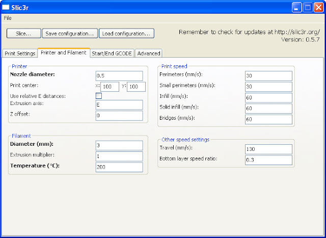
Printer - Nozzle diameter: Slic3r needs to know what nozzle size you have so it can help calculate the width of each path for the selected layer height along with filament diameter (see below) it can then best work out where to place the extrusion paths to get correct infill and perimeters. Your most likely to have a 0.5mm, 0.4mm or 0.35mm nozzle.
Print Center: Your object is placed in the middle of the bed by default, so Slic3r needs to know where that is, some machines have offsets for wider carriages, for a standard Prusa mendel machine 100,100 should be correct. I have a wider X and smaller Y so I use 115, 85.
Use Relative E Distances: Some Firmwares use relative positioning, this makes the Gcode different by stating the distance to the next point from where you are now. Absolute positioning always states the end point regardless of where you are. unless you know your firmware is using Relative do not tick this box.
Z Offset: With this you can set a starting point for your Z axis, you may do this if you use a glass surface for some prints (PLA) and maybe remove the glass for ABS printing, the Z offset for PLA would be the thickness of the glass plate. - I use 0 and set-up my machine to be at the surface of whatever print bed I'm using, this gives you the maximum print height.
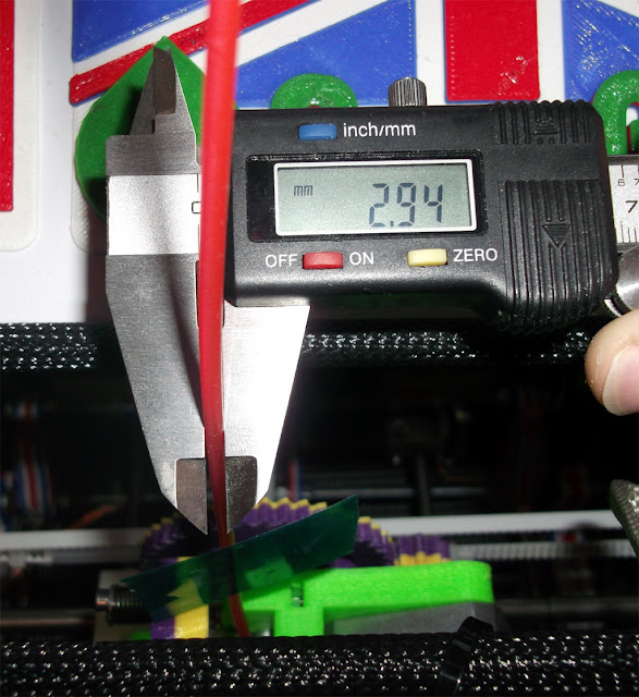
Filament - Diameter: This is really important to get correct, Slic3r needs to accurately know what volume of plastic is being fed into the extruder, so you need to measure the filament really well. Be aware that it may well change from supplier and by batch, and if you are really unlucky by the meter!
Also be aware that 'normal' 3mm filament is usually around 2.75mm but it's also still quite common to get 2.9 from American suppliers and 3.0 or 3.1mm from Chinese sourced suppliers, so it's worth checking what you have and how consistent it is.
You want to be entering this value to two decimal points into Slic3r.
For good filament you are looking for a deviation of +/- 0.1mm or less along a good length of the coil or reel. You don't want it to be 2.75mm then 2.9mm at a different point as that will just mess up your prints.
Also when you do this check that the filament is round and not oval, In my opinion badly oval filament is not worth the bother of trying to use it, reject it back to your supplier.
I have been supplied '3mm' Chinese sourced filament as big as 3.55mm and as small as 2.6mm. Over 3.2mm could block your extruder but the 2.6mm is still usable in a 3mm extruder.
If you are using 1.75mm filament, then it's exactly the same principle as above.
Extrusion multiplier: This is another fudge value, changing it from 1 alters the value you have just entered into the filament Diameter. Some people use this to compensate for different (Soft/Hard) plastic materials sinking into the extruder hobbed bolt more or less, but really your calibrated extruder from Part 1 and the filament diameter is all you need to get correct, so leave this set to 1.
Temperature: Slic3r will add this value into the Gcode so at the start it will wait for the extruder hot-end to warm up to this value before starting the print process, you can still change this value in pronterface at any time during the print. For PLA 185 is a good value, but you may need to increase this depending on your hot-end configuration or if you are printing very fast.
Print Speed - Perimeters (mm/s): This is the speed that outer shell of the part will be printed at, I use 65 for 'normal' printing, 80 for 'fast' printing and below 50 for 'slow'.
Small Perimeters (mm/s): Small islands in a print or holes in a part can be have a different speed ascociated with printing their shells, usually slower than normal perimeters. - I use 55 for 'normal' printing, 65 for 'fast' printing and below 30 for 'slow'.
Infill (mm/s): This is the speed of all the other infill of the object, you can normally go a little faster when doing this, but make sure the filament strands are not breaking apart if you go really fast - I use 80 for 'normal' printing, 130 for 'fast' printing and below 60 for 'slow'.
Solid Infill (mm/s): This is the speed of the any soild infill layers (apart from the very first layer) and you normally go slightly slower than the infill speed. - I use 70 for 'normal' printing, 100 for 'fast' printing and below 60 for 'slow'.
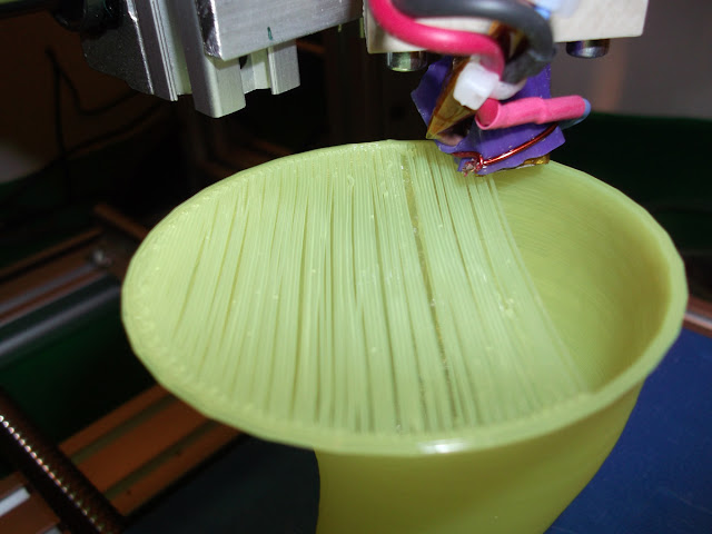
Bridges (mm/s): This is the speed when you a 'bridge' or span filaments across a gap in free-air. It needs testing as temperature, nozzle, and Plastic material makes a big difference to the ability to 'span' gaps.
I use between 35 and 70 here.

Here is the Start Gcode I use - (Suitable for a Prusa with heated bed)
G28 ; home all axes
G92 E0;reset extruder
G1 E3 F1200;Prime extruder 3mm
G1 E2 F1200;retract extruder 1mm
G92 E0;reset extruder
And my End Gcode -
G1 X12.0 F4000 ; home (almost) x - stops extruder crashing into frame if at very top of Z height
G1 Y170 F4000 ; move the print to the front.
M104 S0 ; make sure the extuder is turned off.
M140 S0 ; make sure the bed is turned off.
M84 ; shut down motors.
The only other tab is the Advanced section in here you can specify a Width over Height ratio, but if this is 0 then Slic3r calculates it (very well) for you. So lets' not mess with that.
Remember to save and load your configurations and call them some helpful names, I have a 'draft' (very Quick, little infill) 'normal' ( fast and solid), 'fine' (Lower layer and slower) and a setting for 'hollow pots'
During this test process I have also now another configuration called 'lift' I'll explain that a little more later.
In Part 1 we looked at Print settings and calibrating your extruder.
In this Part 2 will setup the printer, filament and print speeds and then do some printing.
After more settings it's going to get into some level of combining Gcode and optimising print speeds, so any questions, do ask.
Lets take a look at the second Slic3r screen and settings, here are the defaults you will see.

Printer - Nozzle diameter: Slic3r needs to know what nozzle size you have so it can help calculate the width of each path for the selected layer height along with filament diameter (see below) it can then best work out where to place the extrusion paths to get correct infill and perimeters. Your most likely to have a 0.5mm, 0.4mm or 0.35mm nozzle.
Print Center: Your object is placed in the middle of the bed by default, so Slic3r needs to know where that is, some machines have offsets for wider carriages, for a standard Prusa mendel machine 100,100 should be correct. I have a wider X and smaller Y so I use 115, 85.
Use Relative E Distances: Some Firmwares use relative positioning, this makes the Gcode different by stating the distance to the next point from where you are now. Absolute positioning always states the end point regardless of where you are. unless you know your firmware is using Relative do not tick this box.
Z Offset: With this you can set a starting point for your Z axis, you may do this if you use a glass surface for some prints (PLA) and maybe remove the glass for ABS printing, the Z offset for PLA would be the thickness of the glass plate. - I use 0 and set-up my machine to be at the surface of whatever print bed I'm using, this gives you the maximum print height.
Filament - Diameter: This is really important to get correct, Slic3r needs to accurately know what volume of plastic is being fed into the extruder, so you need to measure the filament really well. Be aware that it may well change from supplier and by batch, and if you are really unlucky by the meter!
Also be aware that 'normal' 3mm filament is usually around 2.75mm but it's also still quite common to get 2.9 from American suppliers and 3.0 or 3.1mm from Chinese sourced suppliers, so it's worth checking what you have and how consistent it is.

Use a digital calliper and don't measure it at the very tip, use the bigger middle section as in the photo.
You want to be entering this value to two decimal points into Slic3r.
For good filament you are looking for a deviation of +/- 0.1mm or less along a good length of the coil or reel. You don't want it to be 2.75mm then 2.9mm at a different point as that will just mess up your prints.
Also when you do this check that the filament is round and not oval, In my opinion badly oval filament is not worth the bother of trying to use it, reject it back to your supplier.
I have been supplied '3mm' Chinese sourced filament as big as 3.55mm and as small as 2.6mm. Over 3.2mm could block your extruder but the 2.6mm is still usable in a 3mm extruder.
If you are using 1.75mm filament, then it's exactly the same principle as above.
Extrusion multiplier: This is another fudge value, changing it from 1 alters the value you have just entered into the filament Diameter. Some people use this to compensate for different (Soft/Hard) plastic materials sinking into the extruder hobbed bolt more or less, but really your calibrated extruder from Part 1 and the filament diameter is all you need to get correct, so leave this set to 1.
Temperature: Slic3r will add this value into the Gcode so at the start it will wait for the extruder hot-end to warm up to this value before starting the print process, you can still change this value in pronterface at any time during the print. For PLA 185 is a good value, but you may need to increase this depending on your hot-end configuration or if you are printing very fast.
Print Speed - Perimeters (mm/s): This is the speed that outer shell of the part will be printed at, I use 65 for 'normal' printing, 80 for 'fast' printing and below 50 for 'slow'.
Small Perimeters (mm/s): Small islands in a print or holes in a part can be have a different speed ascociated with printing their shells, usually slower than normal perimeters. - I use 55 for 'normal' printing, 65 for 'fast' printing and below 30 for 'slow'.
Infill (mm/s): This is the speed of all the other infill of the object, you can normally go a little faster when doing this, but make sure the filament strands are not breaking apart if you go really fast - I use 80 for 'normal' printing, 130 for 'fast' printing and below 60 for 'slow'.
Solid Infill (mm/s): This is the speed of the any soild infill layers (apart from the very first layer) and you normally go slightly slower than the infill speed. - I use 70 for 'normal' printing, 100 for 'fast' printing and below 60 for 'slow'.
Bridges (mm/s): This is the speed when you a 'bridge' or span filaments across a gap in free-air. It needs testing as temperature, nozzle, and Plastic material makes a big difference to the ability to 'span' gaps.
I use between 35 and 70 here.

An example of some quite extreme bridging of filament, a slight bow-down but after 3 layers it's flat.
Other speed settings - Travel (mm/s): This is the speed that the machine will accelerate upto when positioning itself before printing and also any in-air moves to a new point before extrusion again.
The maximum speed of your machine will depend on weight of each axis and how much torque the motor can deliver, what bearings you have and how your acceleration speeds have been setup in firmware.
With a low weight print bed and a Bowden extruder machines can run at 300mm/sec
For a Linear bearing Prusa with normal Nema17 Extruder and a heated PCB print bed you can run at 200mm/sec (I use 195mm/sec all the time)
If you have a big metal heated bed on your Y axis or are using PLA bushings then stick to travel speeds lower than 150mm/sec.
Bottom layer speed ratio: This allows you to slow down the very first layer by a factor to help make it stick to the print bed and get a good clean start before part building goes higher.
For my 'normal' speed settings detailed above I use a bottom layer speed ratio of 0.35, this makes things 35% of the speeds you have specified in Perimeter, infill and solid infill for this first print layer.
But how do I know if my print is stuck down well to the print bed?
It depends on what surface you are printing on, I can highly recommend heated Glass as the very best surface I have used for PLA printing and heated Kapton or PET for ABS printing
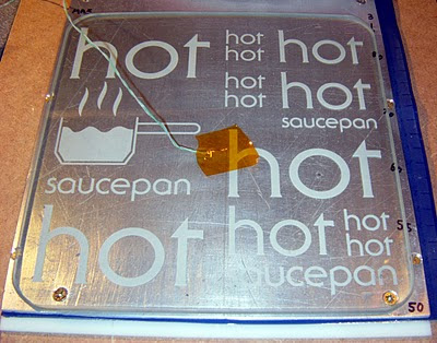
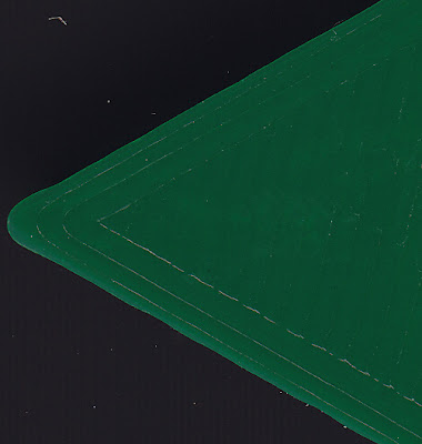
Top Tip - I use 4mm temperature resistant glass, you can get sheets 200mm x200mm with nice ground rounded edges sold in the many 'home shops' up and down the country, they glass trivets to stand hot pans on and are sold for £1-2 each and withstand 200+ degrees C, perfect for our use and they fit very well on a Prusa heated PCB. Some people use plain window glass, but that can shatter or crack easily when hot.

(Old Photo) Temperature resistant glass plate 200mm x 200mm

The rounded corners on the glass allow a Prusa heated PCB to be screwed down flat and you can fix the glass in place by using bulldog clips or I use PET tape at the corners.
Top Tips for glass printing -
- Allow your glass to expand, most people use clips or tape the glass down.
- If you can try to keep the glass fixed to the heated bed, you should not need to remove it.
- Keep your Glass finger print free. - try not to touch the glass, ever.
- I use supermarket brand nail polish remover, just a quick wipe while it's warm keeps it clean.
- Other people use window cleaner or acetone.
- If you don't let the parts or bed to cool and try to lever them off they will bend.
- If you let the parts cool after printing they will pop off the glass all by themselves.
Getting your first layer to stick -
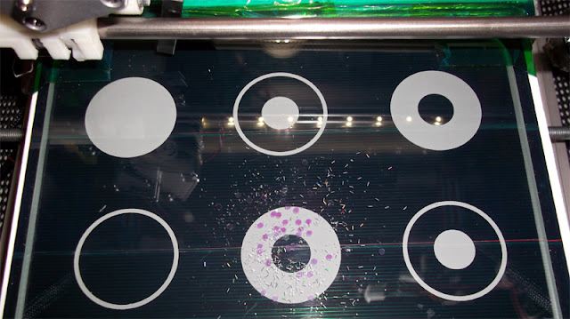
Below are some examples of what the bottom layer of a print should look like, and what to look for when getting the first layer height stuck correctly down to the print bed -
First make sure your bed is level and at 90 degrees to your X carriage bars so things build up straight and true.
I'm currently making the transition to not using springs on my heated bed, even with really hard and tight springs I still believe they are not a good idea for perfect printing quality - More on this in a future post.

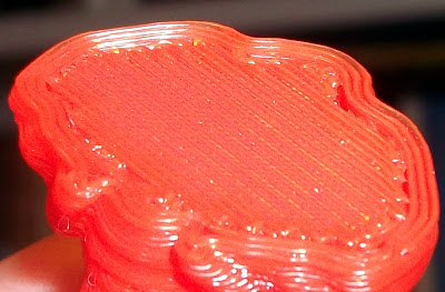
An example of a very over-squashed first layer, this will stick really well but will give you a pronounced ridge on the bottom of your printed object.

Still slightly over-squashed, but fine and a lot of people like this look.

This is hardly stock down at all and popped off the print bed half way into the print.

same print just on an angle so you can see the poor adhesion
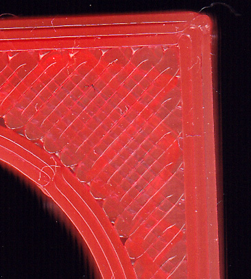
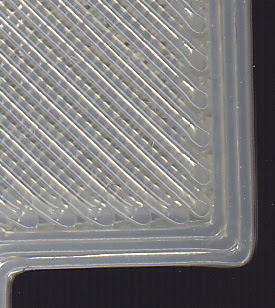
This print is a about perfect for first layer adhesion and minimal distortion.

And another print that I would consider to be perfect adhesion and no bottom layer distortion, this also matches a lot more like all the other sides of the object when printed.
Wow! we got there, all those settings. Now lets take a quick look at Start/End Gcode and then do some printing -
G28 ; home all axes
G92 E0;reset extruder
G1 E3 F1200;Prime extruder 3mm
G1 E2 F1200;retract extruder 1mm
G92 E0;reset extruder
And my End Gcode -
G1 X12.0 F4000 ; home (almost) x - stops extruder crashing into frame if at very top of Z height
G1 Y170 F4000 ; move the print to the front.
M104 S0 ; make sure the extuder is turned off.
M140 S0 ; make sure the bed is turned off.
M84 ; shut down motors.
The only other tab is the Advanced section in here you can specify a Width over Height ratio, but if this is 0 then Slic3r calculates it (very well) for you. So lets' not mess with that.
Remember to save and load your configurations and call them some helpful names, I have a 'draft' (very Quick, little infill) 'normal' ( fast and solid), 'fine' (Lower layer and slower) and a setting for 'hollow pots'
During this test process I have also now another configuration called 'lift' I'll explain that a little more later.
Let's Print !
I'm not going to use any normal calibration objects like the hollow pyramid as some of them show up an issue with Slic3r and the fact it does not yet have a minimum layer time (yet) - I'll explain below -
With just my calibration done and speed settings to 65mm/sec perimeter and 80mm/sec infill, prints of most things come out very well,-

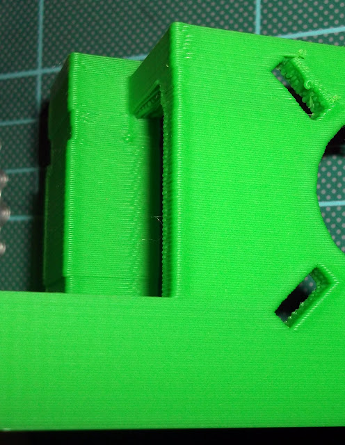
This is a Prusa Z motor bracket at 0.3mm layer height, nice and smooth.
You should now be able to start using Slic3r, everything below here goes a little deeper into printing and optimising printing.
I have selected a few parts that we can analyse how best to print and also this is where we can look at some of the present limitations with Slic3r and how we can get around them, and I hope a few tricks here and there.

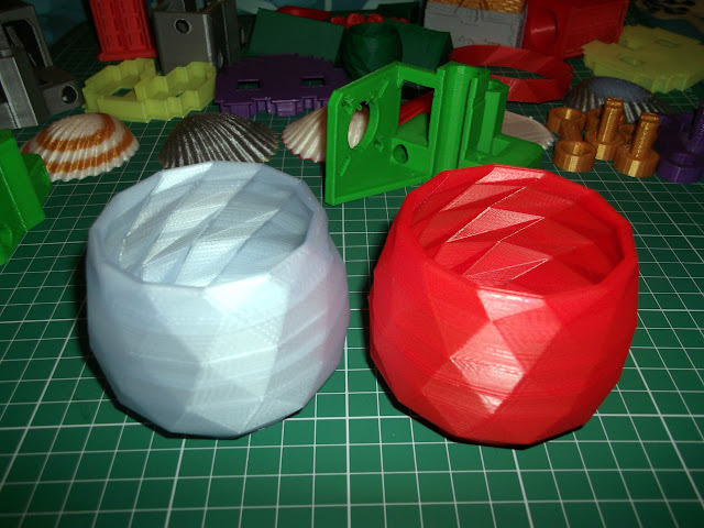
One nice object to try printing is this simple poly cup by WickedAndy, it will help you check you have good layer alignment and it's a nice big but hollow object, quick to slice and print, very satisfying.
These were printed with two perimeters, 25% infill, concentric fill pattern and 0.3mm layer height.
Perimeter speed was 65mm/sec and infill was 80mm/sec.
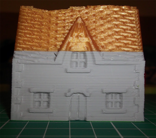
Another nice and easy to slice object is the little stone house by Whistler this is quite a small but detailed building.

Perimeter at 65mm/sec and infill at 80mm/sec - 0.2mm layer height (0.5mm nozzle)
All the normal settings are the same, just the layer height was changed to 0.2mm.
This matt grey PLA is great for seeing defects, it shows every indent and casts a shadow with every bump, any PLA that's shiny or semi-transparent tends to hide defects.
All the normal settings are the same, just the layer height was changed to 0.2mm.
This matt grey PLA is great for seeing defects, it shows every indent and casts a shadow with every bump, any PLA that's shiny or semi-transparent tends to hide defects.

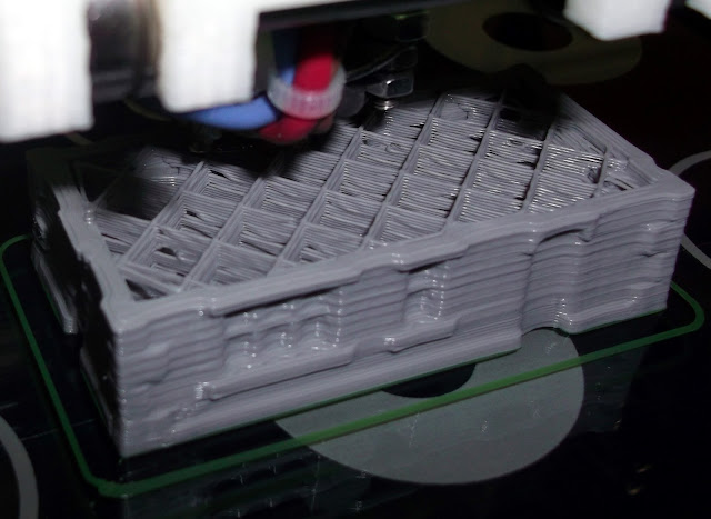
The infill is 10% and as you can see I'm printing it a little too fast so a few infill filaments are breaking.
I'm also using 3 perimeters, two would have been just fine.
I'm also using 3 perimeters, two would have been just fine.

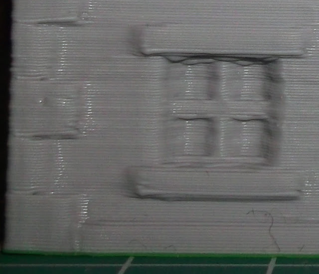
Close-up on the left front window it's (only about 7mm wide) - with a smaller nozzle size the edges of the window will be less curved and have more horizontal detail.
Little video of the house printing - Watch is in Hi-Def Here
Now I'm going to jump straight into a little problem with Slic3r on the next part to print.

The very nice http://www.thingiverse.com/thing:10330 is one of my favourite objects to print, I'm currently printing one in every colour I have.
My links are scales up to 1.75x the size of normal on thingiverse. I print one set of links at a time at 80mm/sec with Skeinforge. This is still very fast for such a small object, but Skeinforge automatically reduces the time to print per layer so it always takes a minimum of 12 seconds to do layers (that's quite slow with such a small part). So it prints the link 'body' very quickly doing 65mm/sec perimeter and 80mm/sec infill, then as it moves up the part and it has less to print so layers slow down and you still get a nice print, by the time it gets to the top it's doing both the perimeter and infill slowly.
Slicer can have a slower 'small perimeter' setting, but it will still do the infill as fast as you set it. When you try to print this object with Slic3r at 80mm/sec it does the body fine but as it moves onto the 'prongs' of the link it's just a total mess of hot plastic being placed much too quickly the object ends up unusable.
Solutions -
You can just slow the whole print down to 20mm/sec, but I don't like waiting for parts especially when I know they can be printed faster with no loss of quality.
So we take advantage of the fact that Slic3r can produce Gcode in just 2.2 seconds for this link and we slice it with different speeds and then combine the gcode at different layer points to get a mixed-gcode-speed printed object. - Don't worry I'll explain how to do that in the next example.

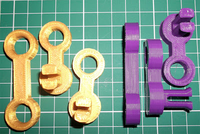
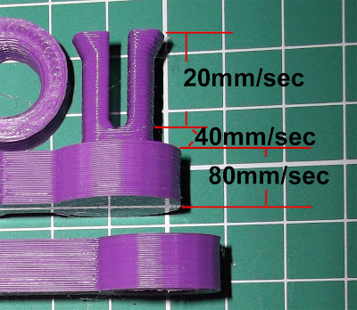
The basic idea is to end up with Gcode at different speeds for the different layers that is compatible with the object you are printing.
In the picture I print the base at 80mm/sec and then the middle at 40mm/sec and the 'prongs' at just 20mm/sec, this produces a very nice print and much faster than if we had printed the whole thing at 20mm/sec.
This method of combining Gcode from Slic3r becomes really important when trying to print other things like the Tardis! below -

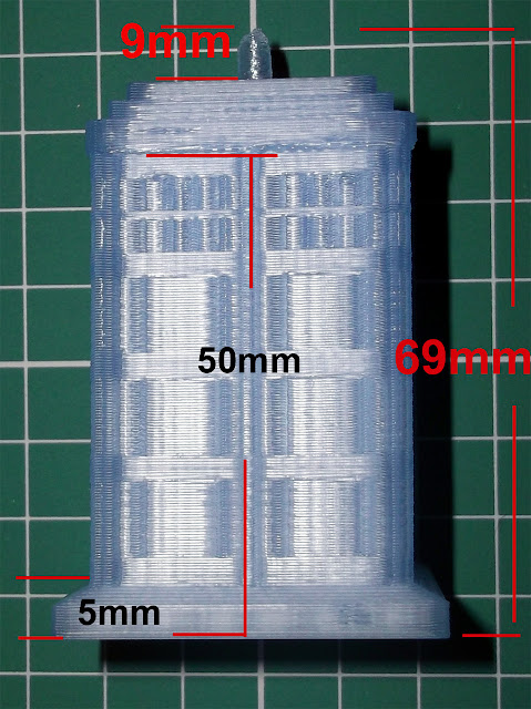
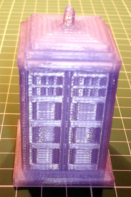
For the Parametric Tardis by Gossamer we have a similar problem, but also we can see other things that would benefit from completely different Gcode as the model changes in height.

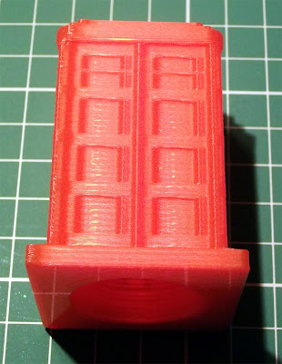
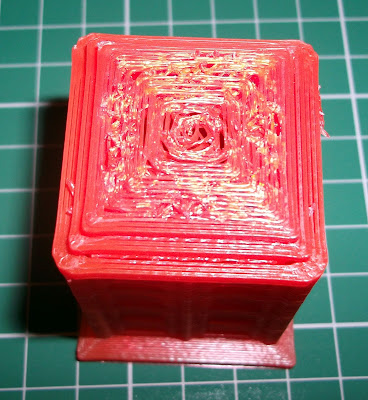
My scaled Tardis model is 69mm High, if I print with a 25% infill it takes 1 hour 30mins to print and makes a mess of the top because it's printing too fast, the light on top is no where to be seen. -

This is the same model but successful printed with the same layer height in just 45 mins print time.
This was done by combining Gcode and doing the following -
- The base section (5mm) needs infill to support the middle section and give support for the slope, if you print this part hollow the base will look very poor.
- The middle section (45mm) can be hollow with no infill at all, just 2 perimeters, this makes if very fast to print and the main reason that this print is half the print time.
- The top part again needs to be printed slower than the body or base and needs infill (25%) to make the top look good and help support the final light on top
- The light needs to be printed very slowly or it will not build.
The point of showing you how to do this is that even when Slic3r does have a minimum time per layer setting you may well still want to combine Gcode for different reasons, like having sections of hollow and solid layers in the same object.

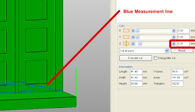
You can 'measure' a model very easily using the basic free version of Netfabb -
This will tell you at what height the parts of the model you are interested in begin (the base line here is showing 5.31mm)

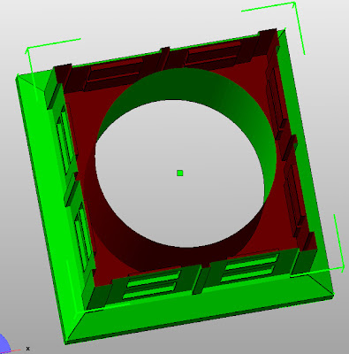
The middle section has already been hollowed out but still has quite an area that would be filled if we sliced it with 25% of infill that we need on the base. It works perfectly well with just a hollow perimeter outline.
With the different 'sets' of Gcode you have generated, you just need to open them up in an editor (I use Textpad) and search for the change in layers - G1 Z
The start of the Gcode is a handy reminder as to the settings you used -
; generated by Slic3r 0.5.7 on 2012-00-08 at 12:09:38
; layer_height = 0.2
; perimeters = 3
; solid_layers = 3
; fill_density = 0.10
; nozzle_diameter = 0.5
; filament_diameter = 2.79
; perimeter_speed = 65
; infill_speed = 80
; travel_speed = 195
; extrusion_width_ratio = 0
; scale = 1
If you search in the Gcode for G1 Z5
you will get to a section of Gcode like this -
G1 F1800.000 E6.50116
G92 E0
G1 Z5.000 F11700.000
G1 X84.707 Y81.055
G1 F1800.000 E1.00000
Everything above the G1 Z5.000 is the object up to 5mm in height, everything below is the rest of the object.
If you replace the Gcode below the G1 Z5.000 with the same objects Gcode but sliced at a different speed or infill then your object will print the original Gcode to 5mm and then the alternative Gcode after that.
You can combine Gcode however you like but for starters I recommend doing it by layer.
In Part 3 of this guide we will combine Gcode with different layer heights, this is another very handy thing when you start to print with very low layers, as you can print the first few at a 'normal height' (0.3mm) to help get a good bond to the bed and level our the surface then switch over to lower height Gcode for the rest of the object. Skeinforge has a setting in 'Skin' to do a similar job of ignoring skin on the first X layers.

Maybe you would not go to this effort for printing one thing, but the next time you think your printing too fast, check if you can selectively slow down some layers or vary the infill of layers to both minimise print time and also maximise print quality.
So hopefully you get the idea, it's good to know more about Gcode, you can find more commands on the Reprap Wiki pages here -
I just wanted to show one more printed object and say how it was printed, as it's a brand new test and technique for me and so far has produced some of the best results I have ever made.

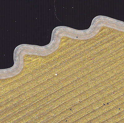
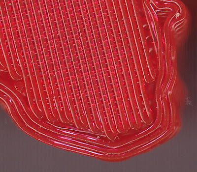
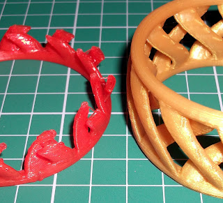
Some of my favourite things on thingiverse are the MakAlot pots and objects, but they are actually quite hard to print, especially if you print them small, you need a well calibrated machine and if you want to print them fast you run the risk of making a mess of your print or it becoming detached from the bed.

I had two prints fail by getting knocked off the bed due to a very tiny surface area (1mm) on the first layer.
they were also a little bumpy (red one on the left)
I tried to print the MakeAlot Link bracelet quite fast and both times it got knocked off the bed about 1/3 into the print, the quality was a little poor and I was about to slow-down the print when I thought this would be a perfect object to test the Z axis 'Lift' setting in Slic3r, I had not tried this before believing that the Prusa mendel Z axis would be too slow and may end up adding extra 'artefacts 'of plastic to the print, I also have my Z axis limited to 4.1mm/sec in Firmware so I was expecting worse results using 'lift'... I was so wrong.

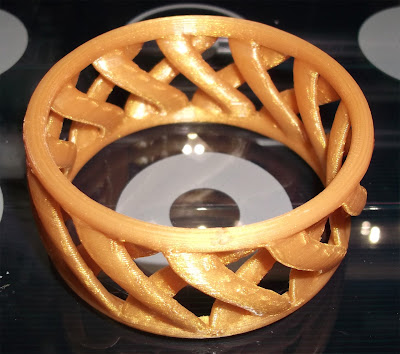
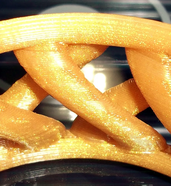
Just using my normal settings for a standard 0.3mm layer height but also a 0.3mm 'lift' on the Z axis.
The print came off the printer as smooth as glass, I'm really impressed with the 'lift' setting, do try it!
I think that I may now be able to print this object the size of a ring, maybe a smaller nozzle would also help.
Thanks to Nophead for pointing out that the Mendel Z axis is fast enough to 'toggle' and use the 'Lift' setting. What I didn't think was that it would help produce such amazing prints, I'm going to try some more of the really complicated MakeAlot pots...
Watch it in Hi-Def Here -
That's all for Part 2, I hope this was useful and if you do nothing else, experiment with a glass bed and the 'lift' setting.
In Part 3 we will experiment with low layer heights using Slic3r.
Thanks for reading.
Rich.
In Part 3 we will experiment with low layer heights using Slic3r.
Thanks for reading.
Rich.
Recommend
About Joyk
Aggregate valuable and interesting links.
Joyk means Joy of geeK