

An almost-GHz active differential oscilloscope probe
source link: http://blog.weinigel.se/2016/02/26/ghz-differential-probe.html
Go to the source link to view the article. You can view the picture content, updated content and better typesetting reading experience. If the link is broken, please click the button below to view the snapshot at that time.
An almost-GHz active differential oscilloscope probe
Feb 26, 2016
I wanted to probe a PCB at work to see how a ~500MHz differential clock was behaving. My trusty 100MHz oscilloscope was no use, it was too slow to see anything and unfortunately I couldn’t quite justify buying a $3k differential probe for my faster scope just for this. There are a bunch of DIY probes to be found on the internet but none that seemed to work really well. But then I thought “how hard can it be?” And thus starts this story.
What I really wanted was an active differential probe which should be able to look at a 500MHz signal at a couple of volts or so with decent fidelity. To do that I wanted a probe with about one GHz of usable bandwidth. I have an old Tektronix 11801B scope with two 20 GHz sampling heads with 50Ω single ended inputs that can handle signals which are 1.0V peak-to-peak so that’s what I wanted the probe output to be compatible with. The probe must attenuate the signal so to not overdrive the inputs and to make things easy to calculate I decided on letting the probe have a 1:10 attenuation.
I have used Tina-TI before and am fairly familiar with it so a natural beginning was to try to simulate the circuit I had in mind in Tina.
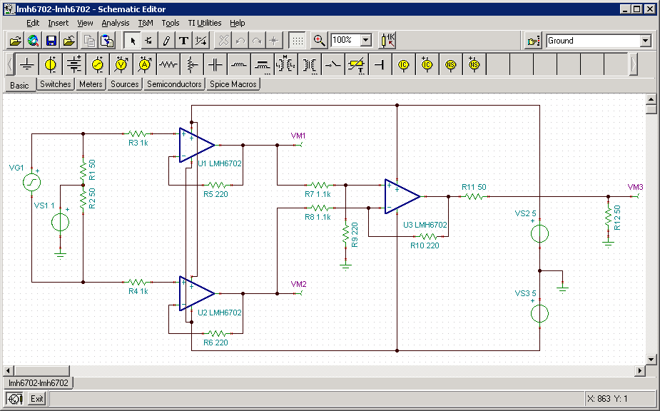
Update: An earlier version of this schematic showed the output of U3 being grounded. That was an error and the ground connection has been removed.
As pointed out by Elliot Williams this is fairly traditional instrumentation amplifier built with separate OP-amps.
I tried a bunch of different OP-amps from the TI libraries but settled on the LMH6702, a “1.7-GHz Ultra-Low Distortion Wideband Op Amp”. It has a high input impedance (1MΩ) when used in a voltage follower configuration and has about twice the bandwidth i need.
The input signal is simulated by a voltage generator (VG1) which outputs a square wave which is then fed to two resistors (R1, R2) centered around a constant voltage source (VS1). This is intended to simulate a 1V LVDS clock signal biased by 1V being fed into a differential termination.
The first stage is a pair of of OP-amps (U1, U2) in voltage-follower configuration. I was a bit worried about oscillation so instead of connecting the voltage follower positive input and feedback directly I’ve added some inputs resistors (R3, R4) and feedback resistors (R5, R6) to avoid this. VM1 and VM2 are measurement points that measure the outputs of the OP-amps.
The second stage is a differencing amplifier (U3) with a less than unity gain (set by R7, R8, R9, R10) which gives a 1:5 attenuation. I’ve read that using an OP-amp to attenuate a signal is supposed to have problems with some OP-amps for reasons having to do with to noise feedback, but it worked in simulation so it should work in real life, shouldn’t it?
Finally there’s a a 50Ω resistor (R11) for impedance matching with the output which together with the 50Ω (R12) termination at the scope input attenuates the signal by 1:2 giving a total attenuation of 1:10 for the whole probe. VM3 measures the signal at the scope input.
VS2 and VS3 are the +5V and -5V voltage supplies for the circuit.
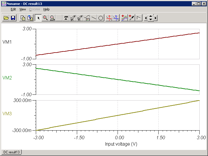
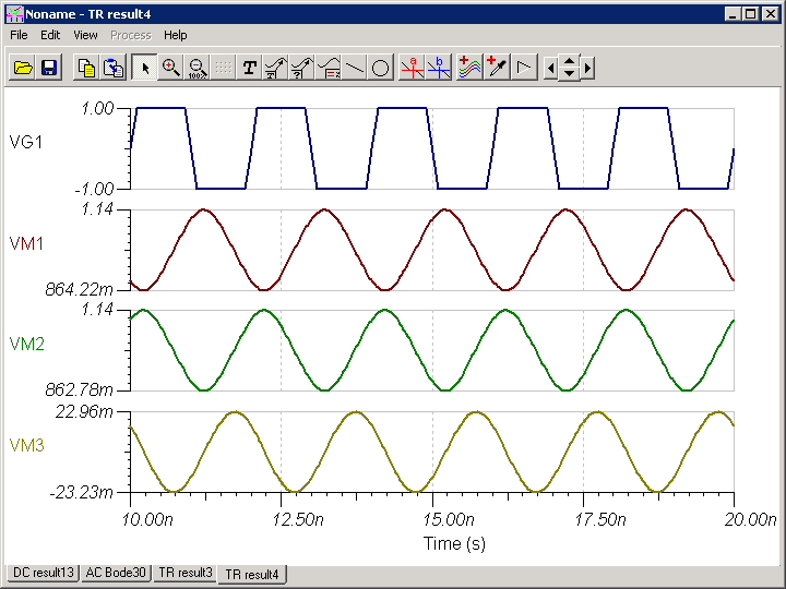
DC performance in simulation looks good. +/-3V at the inputs (X axis) become a +/-300mV signal at the scope (VM3). VM1 and VM2 show the signals after the first stage.
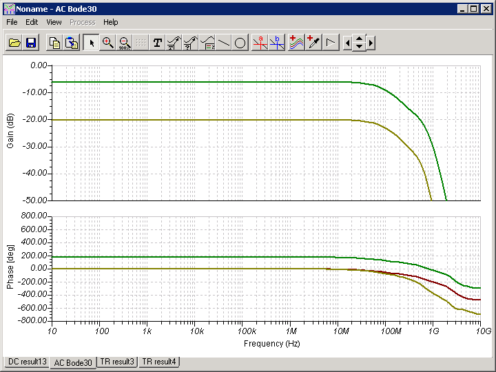
AC performance looks decent. A 1GHz signal signal will be attenuated by 30dB, but a 500MHz signal ought to still be visible on the scope. The phase error doesn’t look to bad, by the time it becomes large the signal should be so attenuated that it doesn’t matter.
A transient simulation of a 100MHz square wave at the input shows that the signal will be attenuated by 1:2 on top of the baseline 1:10 attenuation. Most of the fine details in the signal have disappeared but it should still be possible to measure the frequency and give a rough idea about the quality of the signal.
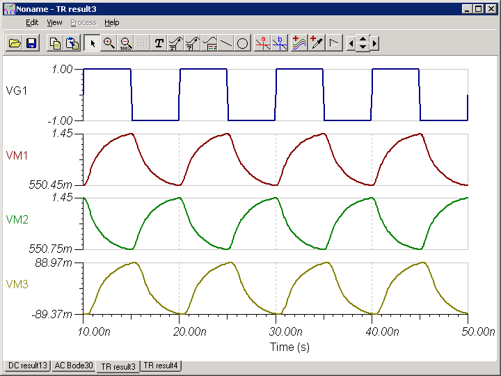
At 500MHz all detail has been lost and we’re basically left with a weak sine wave.
Even though the simulation results wouldn’t fulfill my requirements I decided to create a PCB design in Eagle. I actually created multiple PCB variants with different kind of OP-amps. For good measure I did a single-ended variant too and a small test board with only a SMA connector and a terminating resistor so that I would have something to probe during testing. Each variant also has “stuff options”, space for some extra components that normally won’t be mounted, for example the possibility to add a capacitor in series with the input resistor so that the probe can be AC-coupled instead of DC-coupled.
There’s nothing very special about the PCB. It’s a normal two sided PCB on 1.6mm thick FR4 laminate. I decided to use 0402 components to make everything fit. My hope was also that using such small components togheter with removing the ground plane below the fast signals would reduce stray capacitance which could otherwise compromise signal integrity at high frequencies.
Here’s the PCB I finally sent off for prodution.
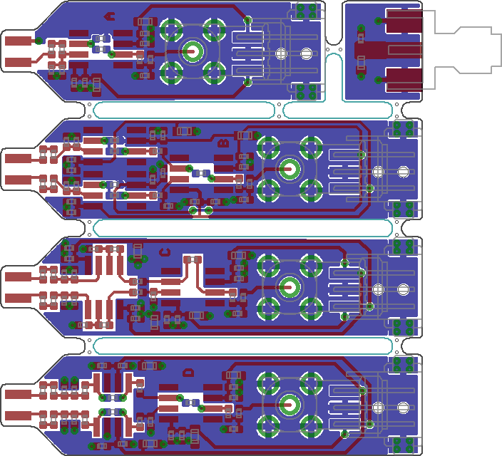
A - Single ended probe with one OP-amp
B - Two standard OP-amps as the first stage
C - Dual OP-amp as the first stage
D - Fully differential OP-amp as the first stage
I have had very good experiences with using Eurocircuits for PCB manufacturing before. Eurocircuits are really good at what they do. It’s possible to upload the Eagle BRD file directly without having to convert it to Gerber format. Their PCB Checker/Visualizer can find issues that could cause problems in production and show you how your finished PCBs will look. The quality of the PCBs is good and they deliver quickly. I can heartily recommend them if you are located in Europe.
It would have been much cheaper to manufacture the PCBs in China but I was impatient. Paying EUR 70 for my PCBs and getting them within a week was much more attractive than paying EUR 10 and then having to wait for a month for the Chinese new year to end before seeing my PCBs.
And I still had that signal I wanted to measure.
Update: This article series is continued in part 2 and part 3
Recommend
About Joyk
Aggregate valuable and interesting links.
Joyk means Joy of geeK