

Developing on NXP's S32K automotive microcontroller - Automotive blog - Arm Comm...
source link: https://community.arm.com/arm-community-blogs/b/automotive-blog/posts/nxp-s32k-automotive-microcontroller
Go to the source link to view the article. You can view the picture content, updated content and better typesetting reading experience. If the link is broken, please click the button below to view the snapshot at that time.
Growing focus on software in vehicles
With ever-increasing consumer demand for enhanced user experiences and personalization in vehicles, the traditional automotive value chain is undergoing disruption. There is a shift happening towards software-defined vehicles. From an OEM standpoint, it opens avenues for new business models by having the ability to launch new features to vehicles in the field. At the same time, users also can add new and enhanced features over the lifetime of the vehicle.
The rising prominence of software has its own challenges. The supply chain is complex with multiple parties. These include chip integrators, vehicle OEMs, Tier1s, operating system vendors, tool vendors and many more. The situation gets more challenging for applications that also require a high level of accuracy and reliability, such as motor control. The rapid growth of electrification has seen the need for more advanced motor control than ever before particularly for hybrid and fully electrified powertrain systems.
This has led to increased demand for automotive processors capable of running computationally intensive algorithms in real-time. NXP´s S32K3 Automotive Microcontroller powered by the Arm® Cortex®-M7 processor is able to perform these algorithms. NXP has brought its extensive automotive experience to further extend the broad ecosystem of software and tools for Arm® based architectures, with the introduction of a Model-Based Design Toolbox (MBDT) to assist in the creation of motor control applications helping to enable a seamless development experience. These models can be applied to almost all electric motor control topologies, including the increasingly popular Permanent Magnet Synchronous (PMSM) and Brushless DC motors (BLDC).
This blog illustrates the challenges associated with motor control software development and describes an approach employing modeling tools to simplify the process. It also covers details about a motor control development kit that enables easy design, test, prototype, and deployment for these applications.
Software development for motor control applications
Embedded software engineers need information on motor properties and characteristics to develop their control algorithms. This means they often rely on in-house motor experts or motor vendors. In addition to core motor control software and hardware engineers, an extended development team also requires mechanical and thermal engineers. These engineers design the overall mechanical packaging and thermal management systems for the entire motor application.
A challenge is how to translate and transfer key information between these groups of engineers without any loss of information. Engineers from different domains prefer to work in their own design environments. This can lead to a lack of information flow between them, reduced collaboration, and inefficient workflows.
Long iteration cycles due to overreliance on hardware-based testing can also create challenges. It takes longer to detect errors and is usually difficult to test all the scenarios. Hardware and software testing is done by a test engineer or an entirely different group. This results in delays in feedback getting to the software developer, causing longer iteration cycles.
For the highest levels of efficiency, high precision control can be achieved using field-oriented control (FOC) on permanent magnet motors, however, this requires complex algorithms. Software engineers need help to better integrate software and verify the control algorithm, ideally with a desktop simulation. They also need help generating compact and fast code from models, to minimize development time using reference examples.
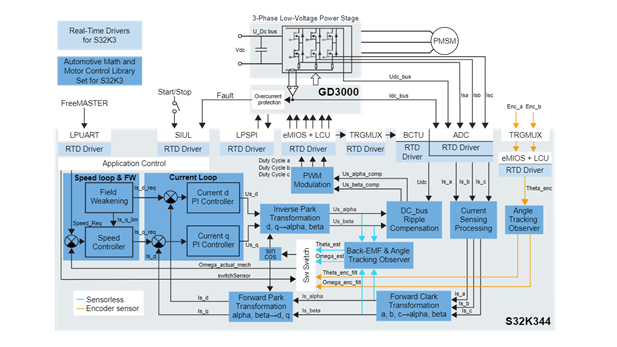
Figure 1: Field-Oriented Control (FOC) implementation with S32K344. Source: NXP
A Solution for faster development
Model-Based Design Toolbox (MBDT) to ease motor control development
Model-Based Design (MBD) is a system engineering approach where mathematical models and visual methods are used to solve complex problems, like control systems, signal processing, or communication. It is used in various fields such as aerospace, automotive, or industrial equipment. MBD can reduce development time and cost by creating a more comprehensive and efficient system development process. This allows engineers to test and optimize their models in a simulation environment, before deploying the algorithms on embedded targets. MBD increases the reusability of the models or subsystems. At the same time, it improves collaboration between different teams, so that various subsystems can be developed, tested, and validated against their requirements. Later, these can be easily integrated together to solve complex tasks, like spinning a motor.
NXP offers its own Model-Based Design Toolbox, a collection of tools and libraries, designed to assist customers with prototyping and accelerating the algorithm development on NXP MCUs. Engineers can model complex algorithms in MATLAB® and Simulink®, and generate embedded code optimized to run on an Arm® Cortex-based MCUs. By using MBDT, engineers can take advantage of its integrated tools, for example, the S32 Configuration Tools (S32CT) for pins, clocks, and peripherals. Once the code is executed on the target, NXP’s FreeMASTER can be used to connect to the running target for tunning or parameter visualization. MBDT can also work in conjunction with some additional MathWorks toolboxes. The most notable include:
- Simscape® for emulating electric motors;
- Stateflow® for easier implementation of finite state machines and application logic; and
- Deep Learning ToolboxTM for designing and implementing deep neural networks with algorithms, pretrained models, and applications.
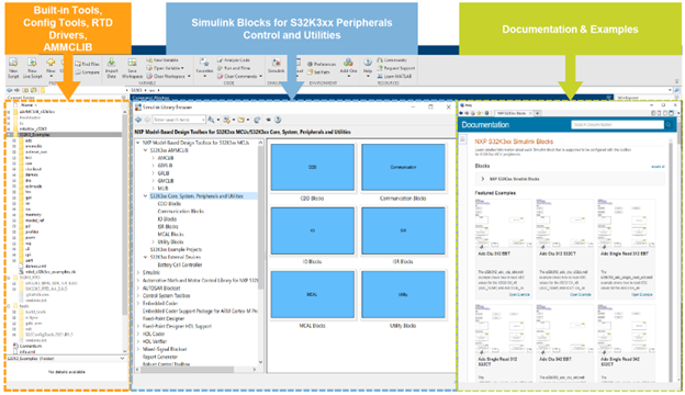
Figure 2: Model-Based Design Toolbox (MBDT) to ease motor control software development. Source: NXP
MBDT for S32K3xx is fully integrated into MATLAB® and Simulink® environment and can be installed directly from the MATLAB Add-Ons or by downloading it from NXP.com. MBDT provides numerous examples alongside documentation for all the blocks it contains. It also integrates the following NXP´s software products:
- Toolchain support, which is the compiler and code deployment mechanism.
- S32 Configuration Tool, which is used for setting the pins, clocks, and peripherals.
- Real Time Drivers (RTD), on top of which the generated code controls the target peripherals.
- Automotive Math and Motor Control Library (AMMCLib), which provideshigh-performance arithmetic, trigonometric, digital signal processing, motor control algorithms and math functions.
- FreeMASTER, with Motor Control Tuning Tool (MCAT) plugin for real-time debug monitoring, data visualization and for runtime configuration and tuning.
Implementation and case study
S32K3 Motor Control Development Kit
The MCSPTE1AK344 is a development kit engineered for three-phase BLDC and PMSM motors. Based on the 32-bit Arm® Cortex®-M7 S32K3 MCU and the GD3000 pre-driver, the MCSPTE1AK344 enables rapid prototyping and evaluation of BLDC and PMSM control applications. The S32K344 microcontroller, delivered with the MCSPTE1AK344, provides suitable peripherals for motor control applications. To spin the motor, the S32K3 MCU delivers PWM signals to the pre-driver, by combining the eMIOS (enhanced Modular IO Subsystem) used to generate high-resolution PWM outputs, together with the LCU (Logic Control Unit) to perform programmable logic functions and fault control. Multiple ADC instances can precisely convert up to three external analog signals at the same time. The BCTU (Body Cross-triggering Unit) can perform ADC triggering to synchronize the PWM generation with the ADC measurements for the motor phase currents. In this chain, additional S32K3xx peripherals could be used. For example, the LPCMP (Low Power Comparator) compares analog values and detects faults, and the TRGMUX (Trigger MUX) routes signal between internal peripherals. In this loop, the Arm® Cortex®–M7 Core processes digital and analog inputs and generates control outputs.
Together with the hardware kit, NXP also provides example software created in the S32 Design Studio (S32DS) IDE built on S32K3 RTD high-level API (AUTOSAR and non-AUTOSAR applications) or low-level API (non-AUTOSAR applications). This demonstrates how the above-mentioned peripherals can work together for a performant motor control application. MCSPTE1AK344 can be used in conjunction with MBDT and MATLAB® Simulink® allowing engineers to design, prototype, test, integrate changes, and deploy to target easily.
MBDT for S32K3 Motor Control Workflow
The MBDT plug-in for S32K3 includes a motor control example that supports the following features:
- Three-phase PMSM FOC driving technique with an operation state machine.
- Current sensing with two shunt resistors.
- Shaft position and speed estimated by sensorless algorithm or encoder position sensor.
- Application control user interface using FreeMASTER debugging tool.
The motor control example is designed around the algorithm which is independent of the MCU target on which it can be deployed. As mentioned before, the advantages here are that the application algorithm can be designed and tested before it is deployed on the real target. By using techniques like Model-in-the-Loop or Software-in-the-Loop, the application can be fed with input test cases and stressed to different scenarios, like short circuit or overcurrent. However, such extreme test cases could be performed in simulation without damaging any real motor.
For example, the Finite State Machine (FSM), which drives the entire system throughout all the defined states to spin the motor, like sensors calibration, rotor alignment, or run state, has been designed using the Stateflow toolbox. It represents a perfect copy of the design mentioned in the planning or requirements stage of the FSM, while the transitions can be easily understood due to its graphical implementation. On top of that, the FSM can be executed like any other piece of code and debugging through breakpoints is possible in case something goes wrong.
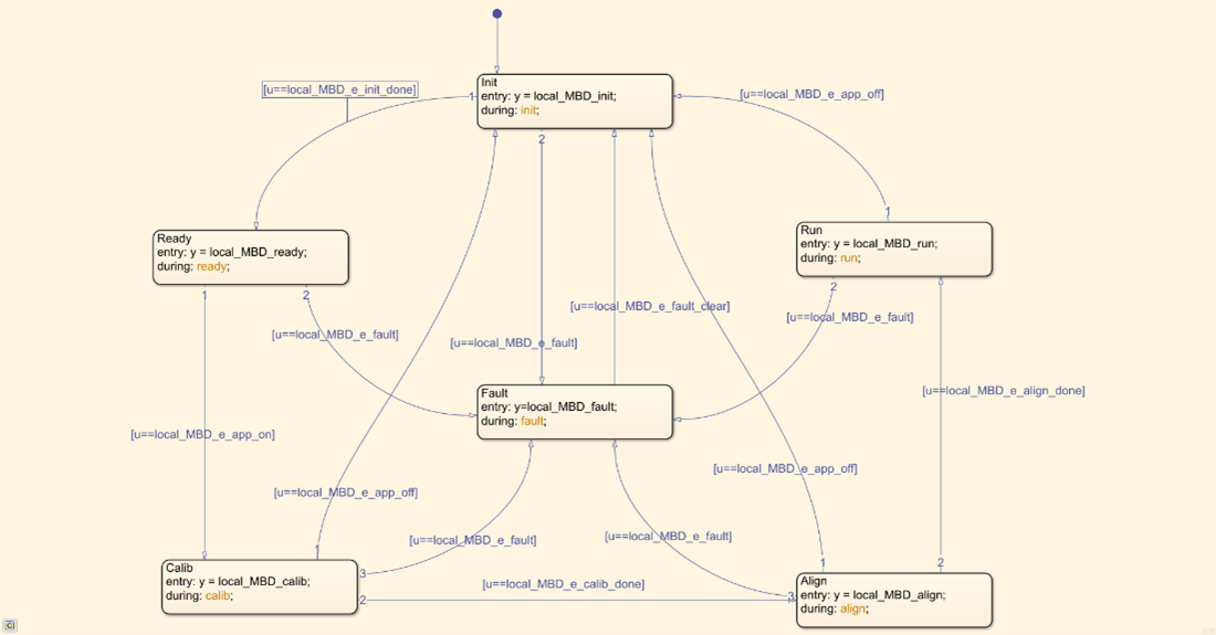
Figure 3: Finite state machine. Source: NXP
The RUN state, receives the measured motor phase currents, performs the complex math computations, and delivers the PWM outputs to the pre-driver. Complex field-oriented control techniques, like Forward or Reversed Park and Clarke transformations, or the Speed and Current loops PID controllers, are implemented using the AMMCLIB library blocks. This library assists automotive embedded applications with high-performance arithmetic, trigonometric, digital signal processing, and motor control functions. It also speeds up motor control development by allowing engineers to focus on the parameter tuning of the algorithms, and not the implementation itself. This Run state design also facilitates the algorithms’ understanding, by allowing a simple follow-up of the signal flow throughout this motor control application technique.
Critical parts of the motor control algorithm, or the entire algorithm, can be tested on the S32K344 in Processor-in-the-Loop mode. This technique is used to automatically generate C code, compile and deploy the code on the target. The execution of the algorithms with the same input vectors, used previously for validating the design in simulation, can now be applied to the target, and validate the correctness of the results delivered by the MCU. The performance of the CPU can also be measured with MBDT by using its embedded profiler capabilities.

Figure 4: Run state. Source: NXP
Once the RUN state has been validated, the model of the control structures fed with the signals, coming from the MBDT control blocks. From the left side of the design, the entire algorithm is triggered by the “Hardware Interrupt Callback”, which is executed when the ADC has successfully performed the motor currents readings. The measurements are translated from RAW register values into currents and the signals are fed to the already validated algorithm. The outputs are then passed to the blocks on the right-hand side, and updated by using the MBDT PWM blocks. However, outputs can be disabled by calling dedicated MBDT blocks for the MCU, which immediately halts the signal generation for the motor pre-drivers, if any fault has occurred.
The configuration of the hardware, like the one mentioned above for the MCU peripherals, together with the ADC, eMIOS, and the synchronization between these peripherals, is performed by using an external configuration tool (S32CT or EB tresos). This tool can be launched directly from the Simulink model. MBDT makes the model hardware aware, by constantly transferring the settings from the external configuration tool project associated with the model, inside the dropdowns of the Simulink blocks. In this way users have access to all the processor parameters and all the hardware configuration settings could be reused easily for some other Simulink projects, by simply importing the Configuration Tool project into the new models.

Figure 5: The top level of the PMSM motor control application in Simulink tool. Source: NXP
Once the code is deployed on the target, the motor rotation can start, and its speed is controlled by pressing the evaluation board push buttons. For monitoring the algorithm together with the online running of some parameters, users can connect to the running application by using NXP’s FreeMASTER.
MBDT enables NXP tools like Automotive Math and Motor Control Library (AMMCLib), compilers, configuration tools, Real-Time Drivers (RTD), and the toolchain in the Simulink® environment. Together with the Embedded Coder®, it generates optimized code for MCUs, ensuring that the most advanced software loops can run on the NXP MCUs with maximum performance.
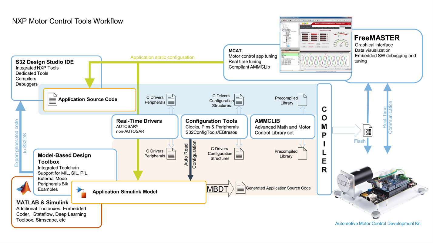
Figure 6: NXP motor controls workflow. This image (source: NXP) shows the workflow of the Motor Control application development using NXP Tools. In the case of MBDT, the application source code is automatically generated from the Simulink model, but the user gets the advantage of the NXP tools.
Conclusion
The importance of software continues to increase in automotive applications due to the rise of Software Defined Vehicles, higher levels of autonomy and electrification. Software development cycle can be simplified and accelerated by offering models, tools, and associated software for complex automotive applications.
MBDT is a gateway between MathWorks´ and NXP´s ecosystems. This enables development benefits for embedded system designs, like simulation, code generation, verification, and validation on NXP’s advanced Automotive microcontrollers such as S32K3. It facilitates an emulation environment for simulating and generating code depending on application requirements. Engineers can therefore design, prototype and deploy software to target in parallel with other teams working on a different part of the overall system.
Visit the MBDT page and the MBDT Community Page to learn more about the features of the Model-Based Design Toolbox for S32K3 and support.
Download the case study: NXP Accelerates Software Creation on S32K Automotive Microcontrollers.
Recommend
About Joyk
Aggregate valuable and interesting links.
Joyk means Joy of geeK